|
High Yield (HY) HIGH STRENGTH STEELS.
AISI Specifications - (CSA SAE) STEELS CHARTS
ALL
WELDS SHOULD FIRST BE PRE-QUALIFIED BEFORE
THE WELD PROCEDURES ARE APPROVED.
HPS.
High Performance "Weathering Steels".
| Steels | Description | Chemistry
weld data | | HPS
70W |
High
performance steel used for bridges. (W) is weathering steel paint not req.
|
For weld information google
Lincoln Electric or ESAB and in the product key words put in weathering steels
to pick your process and consumables. |
High-Yield-strength
steels. (HY-steels.)
| Steels | Yield
ksi
MPa | Tensile
ksi
MPa | Description | Preheat
Post heat | Chemistry |
weld data | | HY80 | 80
-100
551-689 | | | |
carb 0.12 0.18
Mn
0.1-0.4
Si 0.15-0.35
Ni 2 -.3.25
Cr 1-1.8
Mo 0.2/0.6
Ti 0.02
V 0.03
P 0.025 |
For
HY-80-90
E11018-M
E100S-1
E80S-D2
E90T1-K2
|
| HY100 | 100
- 120
689 - 827 | | | | carb
0.12 0.2
Mn 0.1-0.4
Si 0.15-0.35
Ni 2.25/3.5
Cr 1-1.8
Mo
0.2/0.6
Ti 0.02
V 0.03
P 0.025
S 0.025 |
E11018-M
E120S-1
E110T1-K3
|
| HY130 | | | | Preheat
and interpass
<16mm 75-150F
16 to 22mm
125-200f>22mm
200-275f
| | E14018
E120S-1 |
SMAW and GMAW Mechanical Strength
E6010 Minimum Yield 50,000 psi Minimum Tensile 62,000 psi.
E6011 Minimum Yield
50,000 psi Minimum Tensile 62,000 psi.
E7010 Minimum Yield 60,000 psi Minimum
Tensile 72,000 psi.
E7018 Minimum Yield 60,000 psi Minimum Tensile 72,000
psi.
MIG E70S-3-6 Minimum Yield 60,000 psi Minimum Tensile 72,000
psi.
Mechanical Strength of Gas Shielded Flux Cored Electrodes from
the
ANSI / AWS A5.29. 1198 Specification
Low Alloy Steel Electrodes for
Flux Cored Arc Welding
| AWS Classification | Tensile
ksi | Tensile
MPa | Yield
ksi | Yield
Mpa | | E6XTX-X-XM | 60
- 80 | 410
- 550 | 50 | 340 |
| E7XTX-X-XM | 70
- 90 | 480
- 620 | 58 | 400 |
| E8XTX-X-XM | 80
- 100 | 550
- 690 | 68 | 470 |
| E9XTX-X-XM | 90
- 110 | 620
- 760 | 78 | 540 |
| E10XTX-K9-K9M | SEE
SPEC | | 88 | 610 |
| (M)
means an argon mix req, 75 to 80 argon balance CO2 | All
DCEP | E71T-1
Second number
1 = all position
| E70T-1
Second number
0 = flat and horizontal | |
 Brittleness?
The ease at which the weld or metal will break or crack without appreciable deformation.
When a metal gets harder it becomes more brittle. Preheat, inter-pass temp controls
and post heat all are designed to reduce the potential for brittleness. Brittleness?
The ease at which the weld or metal will break or crack without appreciable deformation.
When a metal gets harder it becomes more brittle. Preheat, inter-pass temp controls
and post heat all are designed to reduce the potential for brittleness.
 Weld
Logic: Many manufactures of parts and equipment containing ASTM steels do not
use the recommended pre or post-heat treatments. Weld
Logic: Many manufactures of parts and equipment containing ASTM steels do not
use the recommended pre or post-heat treatments.
The
requirements for weld heat treatment is greatly influenced by many factors, the
application, the governing specifications or codes, the plate condition, plate
thickness, the weld consumables the weld procedures, the weld size and amount
of welds required.
In many cases the manufacturer that uses the high strength ASTM steels will find
that its not necessary for the weld to match the mechanical properties of the
steel, and will therefore typically will utilize low hydrogen, higher ductile
electrodes like SMAW E7018 / MIG E70S-3-6 / FCAW E71T-1.
When using
the low hydrogen electrodes, the pre and post heat treatment recommendations are
frequently eliminated especially on mulltipass welds, however from a weld quality
perspective always ensure that the weld area is dry, the base metal is over 60F,
and that rust and mill scale is removed from the weld area. Also even when heat
treatment is not used, it's beneficial to not allow the multi-pass inter-pass
weld temperatures to exceed 300F
|
Welding
alloy steels often may require unique weld or heat treat considerations. Compare
the low alloy steels chemistry and mechanicals with a standard A36 steel. Remember
this site is only a guide, weld responsibility starts with "you" and
the development of a PQR.
 The
"yield strength".
The stress that can be applied to a base metal or weld without
"permanent deformation" of the metal. The
"yield strength".
The stress that can be applied to a base metal or weld without
"permanent deformation" of the metal.
The
"tensile strength". The ultimate
tensile strength, the maximum tensile strength that the metal or weld can with
stand before "failure occurs".
Metric Conversion 1000 psi = ksi x 6.894
= MPa
AISI SAE DATA AS A GUIDE FOR WELDING
ONLY. ALL WELDS REQUIRE PRE-QUALIFICATION. NOMINAL ALLOY CONTENT MAY BE PROVIDED,
(NOT VERIFIED).
AISI steels. When selecting electrodes take note of;
[a] the carbon content
and the primary alloys.
[b] Over 0.03 carbon ensure low hydrogen electrodes.
[c] Over 0.35% carbon give SPECIAL consideration to pre-heat / inter-pass temp
control and post heat.
THE
FOLLOWING IS A RANDOM SELECTION OF AISI STEELS. THE DATA PROVIDED IS TO ASSIST
WITH YOUR WELDING DECISIONS. TAKE NOTE OF THE PRIMARY ALLOYS THE CARBON CONTENT
AND THEIR RELATIONSHIP BETWEEN THE PRE AND POST HEAT RECOMMENDATIONS.
Weld Procedures intended for weld repairs
on AISI 1040 - 1045 - 1050, forged steel components. The
intention of these weld repairs is to repair cracks, surface scratches or indentations.
With the low hydrogen SMAW (stick) weld process the following recommendations
apply. If cracks occur clean area with grinding or a wire wheel. Drill two 1/8
(3mm) holes within 1/16 (1.6mm) of the weld crack start / stop. Pre-heat and inter
pass temp control is critical to slow down the weld cooling rate to reduce the
hardening effect in the welds and heat affected zone. For these high carbon steels,
a minimum preheat and inter-pass temperature of 600 to 700F is required. Provide
this high preheat with a "propane or natural gas " torch, do not use
acetylene as its conentrated and localized. Provide the preheat on the general
area surrounding the weld repair. Use a temp stick to measure the preheat. Measure
the temp at least 3 to 4 inches from either side of the weld.
 AISI
1040 - 1045 - 1050. SMAW Electrode
Guide Lines: AISI
1040 - 1045 - 1050. SMAW Electrode
Guide Lines:
Use
an E7018 low hydrogen electrode. Polarity DC Reverse Polarity (electrode positive)
or AC. If cracking occurs with the E7018 consider an E312 stainless wire, or the
use of MIG short circuit. Only use SMAW electrodes if they are new and in a sealed
sealed container. Use a small electrode diameter to minimize the required weld
current and heat input. 1/8 or 5/32. No arc strikes are allowed on the part surface,
use a scrap strike plate to establish an arc. Once electrode is warm its easier
to start on shaft. Use stringer, small beads, no weld weaves. At weld completion
gently peen weld bead surface with pointed end of slag hammer to assist in stress
reduction. Maintain preheat during weld. At weld completion wrap insulated blanket
around weld to allow slow controlled cool without drafts to shaft.
ELECTRODE
E7018 DCRP 1/8 130 - 140 AMPS, first choice.
ELECTRODE E7018 DCRP 5/32 140
- 160 AMPS second choice.
If the weld draws lubricant from the shaft and creates a porous weld, grind
out weld, preheat and weld again. After the weld is complete, cooled and ground,
test weld surface area with dye pen.
MIG
Alternative procedures.If
crack issues occur with SMAW on the high carbon steels, consider MIG short circuit
which provides lower weld energy. For the short circuit welds, use an E70S-3 or
E70S-6 wire, size 0.035. Use argon with - 15 to 25%% CO2. Set the 0.035 short
circuit wire feed at 280 ipm, around 11 0'clock. You can measure the wire ipm
by the wire length attained for 10 sec. Set the short circuit weld voltage at
17 to 18 volts, and achieve crisp, consistent crisp crackle. Use stinger beads
and use the preheat and other applicable weld data from SMAW procedure.
AISI SPECIFICATIONS
AISI
- SAE 10XX to 4340 | | Steels | Yield
ksi
MPa | Tensile
ksi
MPa | Description | Preheat
Post heat | UNS/International | Chemistry
Range
Weld Electrodes | AISI/SAE
10XX
|
1005 -1030
45-50
1040
50-60
1050
53- 62 |
1005-1030
60- 80
1040
75-95
1050
92-105
|
Plain
Carbon Steels |
1005
-1023
>50 mm 150F
Post heat desirable 1026/1030
1100F
1030preheat
>13mm 150F.
1035 preheat
<25mm
100F.>25mm 250F post heat desirable 1100F
1040-42-43 preheat
<12mm 200F <25mm 350F>25mm 450F
1045
preheat <13mm 300F >13mm 500F
1040
TO 1049
post heat desirable 1100/1250F
1050 preheat
<12mm 200F <25mm 350F>25mm 450F
|
AISI 1010.
Carbon
0.08/0.13
Mn 0.3 - 0.6
UNS G10100
German
Din 1.1121
Japan S10-12C-S9CK
France XC
AISI 1015
Carbon 0.12/0.18
Mn 0.3 - 0.6
UNS G10150
German 1.1141
Japan SI5CP17CK
Swed 1370
France XC-15-18
AISI
1020
Carbon 0.17/0.23
Mn 0.3 - 0.6
UK
040A2
UNS G10200
German 1.0402
Swed 1450
France CC20 AISI
1030
Carbon 0.27/0.34
Mn 0.6 - 0.9
UNS
G10350
German din 1.0501
UK 060A35-080A32
France CC35
AISI 1040
Carbon 0.36/0.44
Mn 0.6/0.9
UNS G10400
German Din 1.1186
Japan S40C
UK 080 A 40 2S93
AISI 1045
Carbon
0.42/0.50
Mn 0.6/0.9
UNS G10450
France XC 42-45
Germany DIN 1.1191
Japan S45-48c
sweden 1672
AISI
1050
Carbon 0.47/0.55
Mn 0.6/0.9
UNS G10500
German
DIN 1.1210
Japan S 53 C-S 55C
| For
Joining the 10XX grades to 1035
E7016-18
E70S-X
E7XT-1
For grades > 1037 to 1050 use E70XX, 7018 or E8018
|
| AISI/SAE
1137
AISI/SAE
1140
AISI
1144 |
50
- 55
|
84 - 91
| |
preheat <13 mm
100F <25 mm 150F > 25mm 250F
preheat
<13mm 200F <25mm 300F >25mm 350f |
UNS G11370
UNS
G 11400
SWE 1957
France 35 mf 4
Germany 1.0726
C.
0.04 -0.048
Mn. 1.35 -1.65
S. 0.24- 0.33.
Note
high sulfur most welds will crack | carb
0.32-0.39
Mn 1.35/1.65
E7016-18
E70S-X
E7XT-1
E8016-18
carb 0.37-0.44
Mn 0.7-1
E7016-18
E70S-X
E7XT-1
E8016-18
E70S-X
E7XT-1
Use
312 if welded to stainless
|
AISI/SAE
1330 |
| |
Manganese
steel
| preheat
<13mm 250F >13mm 350 F |
UNS
G13300
Germany DIN 1.1165
Japan SMn1h SCMN2
|
carb
0.27-0.33
Mn 1.6 -1.9
Si 0.15 -0.35
E7016-18
E70S-X
E7XT-1
E8016-18
|
AISI/SAE
1340 |
63
- 82 |
100-121 |
Manganese
steels |
preheat
<25mm 400
>25 mm 550
if >25mm hold at 550F for an hour per
inch after welding
|
UNS
G13400 Germany
Din 15069
| carb
0.38-0.43
Mn 1.6/1.9
Si 0.15/0.3
E10016-D2
E80S-D2
E100T5-D2
|
AISI/SAE
15XX |
| | | | | carb
0.1-0.52
Mn 0.8/1.65
|
AISI/SAE
23XX
|
| | | | | Ni
3.5 |
AISI/SAE
25XX |
|
| | | | Ni
5 |
AISI/SAE
31XX
|
|
| | | | Ni
1.25
Cr 0.65/0.8 |
AISI/SAE
32XX |
| | | | | Ni
1.75
Cr 1.07 |
AISI/SAE
33XX |
| | | | | Ni
3.5
Cr 1.5-1.57 |
AISI/SAE
34XX |
| | | | | Ni
3
Cr 0.77 |
AISI/SAE
4023 |
Molybdenum |
| note
concern for filler metal if quenched and tempered after weld |
Preheat
>13 mm 150f
post heat desirable 1100F |
UNS
G40230 |
carb 0.2/0.25
Si 0.15/0.3
Mn0.7/0.9
Mo0.2/0.3
E7018-A1
E70S-X
E7XT-5
E8016-18
|
AISI/SAE
4130
|
Chrome/moly |
51-65 |
80 -100 from as rolled normalized or annealed only | Preheat
<13mm 300F
<25 mm 400F
>25mm 450F |
UNS
G41300
UK CDS 110
Germany DIN 17218
Japan SCM/2
Swe 2225
|
Carb
0.27/0.34
Mn 0.35/0.6
Cr 0.8/1.15
Mo /0.25.
SI 0.15-0.35
As welded
E8018-B2
E9018B2
QUENCHED AND TEMP
Flux cored
4130 basic
|
AISI/SAE
43XX 4340 | Ni/Cr/Mo |
4340
67-125 |
4340
107-187 |
| 4340
Ger Din 1.6562
JP 40NiCrMo7
UK8S 139
WELD
E120-M
Preheat 300 C
post heat treat necessary. Watch for HAZ and weld cracks from
restrained or undersize welds |
Carb
0.17/0.44
Ni 1.65/2
Cr 0.4/0.9
Mo 0.2/0.3.
Gas shielded
flux cored 4340 available from Postle industries Cleveland |
Note on 4140. If no post heat treat I would use the ESAB Dual Shield 11-70T- 12HR with Argon 25 CO2. Or the Dual Shield 11-71 Ultra if using straight CO2.
Note High pre-heat / interpass required, 550 - 650F. Use blanket for slow cooling. Parts less than one inch, < 25 mm use 0.045 wire. Parts over 25 mm I i would use the 052 wire
Ultrahigh-Strength
Steels are commercial
structural steels capable of a minimum yield strength of
1,380 MPa (200 ksi).Three types of these steels are;
[1] Medium
carbon, low alloy,
[2] medium alloy, air hardening,
[3] Hgh alloy, hardenable
steels.
The common medium carbon low-alloy steels, such as 4130,
4140, 4340, and 8640, generally are supplied by the mill in either the
normalized and tempered or annealed condition and are readily forged. Alloy 4130
is a water-hardening alloy steel of low to intermediate hardenability. Because
4130 steel has low hardenability, section thickness must be considered when heat
treating to high hardness or strength.
E-Mail
Feb 2007.
Hi Ed. Would you offer some advice on welding 4130
plate and tubing using GMAW? I have looked in the books that we have of yours
and have searched the discussion group and didn’t find similar enough situations
for reference. The weldment consists of 4130 sheet/plate and pipe that is heat
treated to 125-145 KSI ultimate tensile strength prior to welding. The sheet/plates
range from .125”-.625” thick and the tubes range from .188”-.250”
wall thickness. I will be using a 120 KSI UTS filler metal and the weldment will
be post weld stress relieved. Do you have any suggestions on the parameters and
techniques that should be applied? Thanks, Steve
From Mike. Why not use a 4130 filler metal. I have been involved with welding
a structural component for the last four years. We have had excellent results.
The base metal is supplied in the annealed condition. The component is pre-heated
to 400F and then subjected to post weld hest treatment. In a few instances, due
to engineering changes after the pwht, some minor welds were made and a local
pwht was applied.
From
Ed. Steve welding with or without heat treatment, its logical to use low end parameters,
use stringers, avoid weaves and maintain an interpass temp of 300F max.
Manganese
Steel is sometimes
called "austenitic manganese steel" because of it's metallurgical structure.
This steel is also called Hadfield manganese steel after its inventor. Manganese
steel is an extremely tough, nonmagnetic alloy with extremely high tensile strength
and a high percentage of ductility This steel has excellent wear resistance and
a high resistance to impact.
Note: Manganese steel is almost impossible
to machine.
Manganese steel is widely used as castings and also available
as rolled shapes. Manganese steel is often used for impact wear resistance applications
such as railroad components, steel mill parts and parts on equipment in quarries.
The composition
of austenitic manganese is from 12-14% manganese and 1-1.4% carbon. The composition
of cast manganese steel would be 12% manganese and 1.2% carbon. Nickel is oftentimes
added to the composition of the rolled manganese steel.
To
attain the material toughness of the manganese steel, a special heat treatment
of 1850°F (1008°C) followed by quenching in water is required. To have
minimal impact on the steels properties, special attention is required for welding
or heating. Manganese steel can be welded to itself or to carbon and alloy steels.
Clad weld deposits can be made on manganese steels.
Manganese
steel can be cut with oxy-fuel cutting, keep the base metal as cool as possible.
If the mass of the part to be cut is large its doubtful the heat build will cause
embrittlement. If the parts to ber cut are thin, it's recommended the parts be
cooled or partially submerged in water during the flame cutting operation. For
removal of defects or cracks in the manganese part, the air gouging process can
be used. While doing repairs, again the base metal must be kept cool. Grinding
should be used to smooth up the surfaces for welds.
MANGANESE
ELECTRODE 1. There are two types of manganese steel electrodes available. Both
are similar in analysis to the base metal but with the addition of elements which
maintain the toughness of the weld deposit without quenching. The EFeMn-A electrode
is known as the nickel manganese electrode and contains from 3-5% nickel in addition
to the 12-14% manganese. The carbon is lower than normal manganese ranging from
0.50 to 0.90%. The weld deposits of this electrode on large manganese castings
will result in a tough deposit due to the rapid cooling of the weld metal. The
manganese nickel steel is more often used as a buildup deposit to maintain the
characteristics of manganese steel when surfacing is required.
MANGANESE
ELECTRODE 2. The other electrode used is a molybdenum-manganese steel type EFeMn-B.
This electrode contains 0.6-1.4% molybdenum instead of the nickel. This electrode
is less often used for repair welding of manganese steel or for joining manganese
steel itself or to carbon steel.
MANGANESE
ELECTRODE 3. Stainless steel electrodes can also be used for welding manganese
steels and for welding them to carbon and low-alloy steels. The 18-8 chrome-nickel
types are popular; however, in some cases when welding to alloy steels the 29-9
nickel is sometimes used. These electrodes are considerably more expensive than
the manganese steel electrode and for this reason are not popular.
STRESS
RELIEVING:
STRESS
RELIEF - CONTROLLED HEATING & COOLING TO REDUCE STRESSES.
STRESS
RELIEF MACHINED PARTS FOR DIMENSIONAL STABILITY.
STRESS
RELIEF SLOW HEATING AND COOLING REQUIRED
CONFIRM
WITH CODE SPECIFICAIONS FOR STRESS RELIEF REQUIREMENTS.
| TYPICAL
STRESS RELIEF SOAK TIME
ONE HOUR PER INCH OF THICKNESS | SR
HEAT & COOL RATE PER HOUR 400oF 204oC DIVIDE THICKER PART |
PARTS
OF DIFFERENT THICKNESSES
SR MAX TEMP DIFFERENCE 75oF 24oC | STRESS
RELIEF CARBON STEELS 1100oF 593oC
TO 1250oF 677oC |
STRESS RELIEF
CARBON 0.5% Mo
1100oF 593oC TO 1250oF 677oC | SR
1% CHROME 0.5% Mo
1150oF 621oC TO 1325oF 718oC |
SR 1.25
% CHROME 0.5% Mo
1150oF 621oC TO 1325oF 718oC | SR
2% CHROME 0.5% Mo
1150oF 621oC TO 1325oF 718oC |
SR 2.25
% CHROME 1% Mo
1200oF 649oC TO 1375oF 746oC | SR
5% CHROME 0.5% Mo
1200oF 649oC TO 1375oF 746oC |
SR 7% CHROME
0.5% Mo
1300oF 704oC TO 1400oF 760oC | SR
9% CHROME 1% Mo
1300oF 704oC TO 1400oF 760oC | SR
12% CHROME 410 STEEL
1550oF 843oC TO 1600oF 871oC | SR
16% CHROME 430 STEEL
1400oF 760oC TO 1500oF 815oC |
SR 9% NICKEL
1025oF 552oC TO 1085oF 585oC | FOR
300 SERIES STAINLESS SR WILL
RESULT IN CARBIDE PRECIPITATION |
WITH
LOW CARBON 300 SERIES
MAX SR 1050oF 566oC | SR
400 SERIES CLAD STAINLESS
1100oF 593oC TO 1350oF 732oC |
SR
CLAD MONEL INCONEL Cu NICKEL
1150oF 621oC TO 1200oF 649oC | STRESS
RELIEF MAGNESIUM AZ31B 0
500oF 260oC 15 MIN | STRESS
RELIEF MAGNESIUM AZ31B
H24 300oF 149oC 60 MIN |
HK31A H24 550oF 288oC
30 MIN
HM21A T8-T81 700oF 371oC 30 MIN
|
MAGNESIUM
WITH MORE THAN 1.5%
ALUMINUM STRESS RELIEF | MAGNESIUM
CAST ALLOYS AM100A
500oF 260oC 60 MIN | AZ-63A
81A 91C & 92A
500oF 260oC 60 MIN | |
Free
Machining Steels.The
term "free machining" can apply to many metals but is normally associated
with steel and brass. Free machining is the property that makes machining easy
because small cutting chips are formed. This characteristic is given to steel
by sulfur and in some cases by lead. It is given to brass by lead.
Sulfur
and lead are not considered alloying elements. In general, they are considered
impurities in the steel. The specifications for steel show a maximum amount of
sulfur as 0.040% with the actual sulfur content running lower, in the neighborhood
of 0.030%. Lead is usually not mentioned in steel specifications since it is not
expected and is considered a "tramp" element. Lead is sometimes purposely
added to steel to give it free-machining properties.
Free-machining
steels are usually specified for parts that require a considerable amount of machine
tool work. The addition of the sulfur makes the steel easier to turn, drill, mill,
etc., even though the hardness is the same as a steel of the same composition
without the sulfur. The sulfur content of free-machining steels will range from
0.07-0.12% as high as 0.24-0.33%. The amount of sulfur is specified in the AISI
or other specifications for carbon steels. Sulfur is not added to any of the alloy
steels. Leaded grades comparable to 12L14 and 11L18 are available.
Unless
the correct welding procedure is used, the weld deposits on free-machining steel
will always be porous and will not provide properties normally expected of a steel
of the analysis but without the sulfur or lead.
The
basis for establishing a welding procedure for free-machining steels is the same
as that required for carbon steels of the same analysis. These steels usually
run from 0.010% carbon to as high as 1.0% carbon. They may also contain manganese
ranging from 0.30% to as high as 1.65%. Therefore, the procedure is based on these
elements. If the steels are free-machining and contain a high percentage of sulfur
the only change in procedure is to change to a low-hydrogen type weld deposit.
In
the case of shielded metal arc welding this means the use of low-hydrogen type
electrode such as EXXX8 classification. In the case of gas metal arc welding or
flux-cored arc welding the same type of filler metal is specified as is normally
used since these are no-hydrogen welding processes.
Submerged
arc welding would not normally be used on free-machining steels. Gas tungsten
arc welding is not normally used since free-machining steels are used in thicker
sections which are not usually welded with the GTAW process.
For the worlds
best MIG and flux cored weld
process control training resources vist here.
 Fatigue.The
ability of a metal or weld to withstand repeated loads. Fatigue failures occur
at stress levels less than the metal or weld yield strength. Some things that
can influence fatigue failure: Fatigue.The
ability of a metal or weld to withstand repeated loads. Fatigue failures occur
at stress levels less than the metal or weld yield strength. Some things that
can influence fatigue failure:
Excess
weld profiles.
Welds
which cause undercut.
FCAW
or SMAW slag inclusions.
Lack
of weld penetration.
Excess
weld heat, typically from multi-pass welds without inter-pass temp controls.
Items
to a part that adds restraint while welding.
Items
added to a part that can concentrate stresses in a specific location.
Incorrect
selection of filler metal, weld too weak or weld too strong.|
AISI
/ SAE 44XX TO 98XX STEELS. | | Steels | Yield
ksi
MPa | Tensile
ksi
MPa | Description | Preheat
Post heat | UNS | Chemistry
weld data | AISI/SAE
44XX
|
| | Moly
Steel |
4419
preheat >13mm 100F .>25mm 200F
4419/4422/4427
post heat required
FOR 4419/4422/4427
at 1200-1350F |
|
SAE 4419
carb 0.18-0.23
Mn 0.45-0.65
Si 0.15-0.3
Mo0.45 - 0.6
| AISI/SAE
46XX
|
4620
53-55 |
4620
75-85 |
Ni-Moly |
4615 - 4617- 4620
preheat >13mm 200F >25 mm 250 F post
heat desirable 1100-1250F | |
4615
carb
0.12-0.18
Mn 0.4/0.65
Si 0.3
Ni 1.65/2
Mo 0.2/0.3 weld
4620
E8018-C1
E80S-D2
E81T1-Ni2
|
AISI/SAE
47XX |
| | Ni
- Cr - Mo |
| |
carb 0.16-0.22
Ni 0.9-1.2
Cr0.35-0.55
Mo 0.15/0.4
| AISI/SAE
48XX |
| | Ni-
Mo |
| | carb
0.13-0.23
Ni 3.25-3.75
Mo 0.2 /0.3
|
AISI/SAE
50XX |
| | Carb/Chrome |
AISI
5046 preheat <13mm 300 F <25MM 350F >25mm 400F |
| 50xx
range
carb 0.12-0.48
Mn 0.3/1
Si 0.15-0.35
Cr 0.2-0.6 |
AISI/SAE
51XX
|
| | Carb/Chrome
HIGHER CHROME THAN 50XX |
AISI
5120
E8016-B2
E80T1-B2
>13mm 250F post heat desirable
1100 to 1250F |
| 51xx
range
carb 0.13-0.53
Mn 0.6/0.9
Si 0.15-0.35
Cr 0.7-1.15
|
AISI/SAE
61XX |
|
| Cr
/ V |
| | carb
0.16-0.54
Mn 0.5/0.9
Cr 0.5-1.15
V 0.1-0.15
|
AISI/SAE
81XX
|
|
| Ni
/ Cr / Mo |
| | carb
0.13-0.18
Ni 0.2/0.4
Mo.0.08-0.15
Cr 0.3-0.5 |
AISI/SAE
86XX |
| | Ni
Cr Mo |
| | carb
0.12 /
0.48
Ni 0.4/0.7
Mo.0.15-0.25
Cr 0.35-0.6 |
AISI/SAE
87XX |
| | Ni
Cr Mo |
| | carb
0.18-0.46
Ni 0.4/0.7
Mo.0.2-0.3
Cr 0.35-0.6 |
AISI/SAE
88XX |
| | Ni
Cr Mo |
| | carb
0.2-0.25
Ni 0.4/0.7
Mo.0.3-0.4
Cr 0.4-0.6 |
AISI/SAE
93XX |
| | Ni
Cr Mo |
| | Ni
3.25
Cr 1.2
Mo 0.12 |
AISI/SAE
94XX
|
| | Ni
Cr Mo |
| | Ni
0.45
Cr 0.4
Mo 0.12 |
| AISI/SAE
97XX AISI/SAE
98 XX | | | Ni
Cr Mo |
| | Ni
0.55
Cr 0.2
Mo 0.2
Ni 1
Cr 0.8
Mo 0.25
|
AISI SAE HIGH STRENGTH SHEET STEEL DESIGNATIONS:
AISI 035SF. First three digits = minimum yield 35 ksi (241 MPa)
035SF First
letter after numbers denotes chemistry composition
(S) = structural quality
C-Mn-p-n,
(X) = low alloy Cb-Ti-V-Si-Zr
(W) = weathering steels Si-P-Cu-Ni-Cr
(D) = Dual phase Matensite transformation
AISI
035SF Last letter denotes deoxidation practice. (F) Deoxidation Killed Steel Inclusion
control. (K) Deoxidation killed steel. (O) Deoxidation is none killed. To find
heat treat, chemistry and weld data cross reference these steels with the following
ASTM Steels. Go back to the steels program home page to find your ASTM steel.
AISI
035SK to AISI 080XF | | AISI
Steels | Cross
Reference to ASTM steel Designations |
| | | AISI
035SK | Cross
Ref
ASTM A414/A446 | AISI
035SO | Cross
Ref
ASTM A414/A446
A570 / A611 | | AISI
040SO | Cross
Ref
ASTM A570 Gr 40
A446 A611 |
AISI
040SK
| Cross
Ref
ASTM A414/A570/A611 | AISI
045SK | Cross
Ref
ASTM A579 | AISI
045SO | Cross
Ref
ASTM A570 Gr 45 | AISI
045XK | Cross
Ref
ASTM A607 | AISI
045X0 | Cross
Ref
ASTM A607 Gr45 CL 1 | AISI
045WK | Cross
Ref
ASTM A606 | AISI
050SK | Cross
Ref
ASTM A570 | AISI
050S0 | Cross
Ref
ASTM A446/570 GR 50 | AISI
050XF | Cross
Ref
ASTM A715 | AISI
050XK | Cross
Ref
ASTM A606/A607/
A715 Gr 50
A816 GR 50 Type 2 |
AISI
050X0 | Cross
Ref
ASTM A607 Gr 50-1
| AISI
050WF | Cross
Ref
ASTM A606 | AISI
050WK | Cross
Ref
ASTM A606 | AISI
055XK | Cross
Ref
ASTM A607 | AISI
055X0 | Cross
Ref
ASTM S607 Gr 55 CL 1-2 | AISI
060XF
| Cross
Ref
ASTM A715 | AISI
060XK | Cross
Ref
ASTM A607/A715-60
A816-60
| AISI
060X0 | Cross
Ref
ASTM A607 Gr 60-1-2
A816M Gr 60 type 1 |
AISI
065XK | Cross
Ref
ASTM A607 | AISI
065X0 | Cross
Ref
ASTM A607 Gr 65 CL2 | AISI
070XF | Cross
Ref
ASTM A715 | AISI
070XK | Cross
Ref
ASTM A607 / A715 Gr 70 | AISI
080S0 | Cross
Ref
ASTM A446/A611 Gr E | AISI
080XF | Cross
Ref
ASTM A715 |
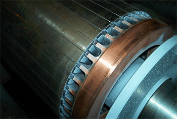 Silicon
Steels or electrical steels, are steels that contain from 0.5%
to almost 5% silicon but with low carbon and low sulfur and phosphorous. These
steels are provided as sheet or strip and used frequently in punched or stamped
applications such as laminations for electrical machinery.The silicon steels are
designed to have lower hysteresis and eddy current losses than plain steel when
used in magnetic circuits. Silicon
Steels or electrical steels, are steels that contain from 0.5%
to almost 5% silicon but with low carbon and low sulfur and phosphorous. These
steels are provided as sheet or strip and used frequently in punched or stamped
applications such as laminations for electrical machinery.The silicon steels are
designed to have lower hysteresis and eddy current losses than plain steel when
used in magnetic circuits.
Silicon
steel stampings are used in the laminations of electric motor armatures, rotors,
and generators. They are widely used in transformers for the electrical power
industry and for transformers, chokes, and other components in the electronics
industry.
For
the laminations welds, the welds are made on the edge of each sheet to hold the
stack together. Almost all of the arc welding processes are used, MIG, submerged
arc, shielded metal arc, gas metal arc, gas tungsten arc and plasma arc welding.
When the consumable
electrode processes are used the stampings are usually indented to allow for deposition
of filler metal. For gas tungsten arc and plasma arc the filler metals are frequently
not used and the edges are simply fused. The size of the weld bead should be kept
at minimum so that eddy currents are not conducted between laminations in the
electrical stack.
One
precaution that should be taken in welding silicon steel laminations is to make
sure that the laminations are tightly pressed together and that all of the oil
used for protection and used in manufacturing is at a minimum. Oil can cause porosity
in the welds which might be detrimental to the lamination assembly.
 Hardness? Hardness?
The resistance of the metal or the weld to penetration.
Hardness is related to the strength of the metal. A good way to test a weld after
the weld and heat treatment are complete, is to test the hardness of weld and
the base metal surrounding the weld.
 Ductility? Ductility?
The amount that a metal or weld will deform without breaking. Measured
on welds by the % of elongation in a 2 inch 51 mm test piece. An E71T-1 flux cored
electrode should result in a minimum of 20% elongation. An E70S--6 MIG weld should
produce approx 22%.
 Toughness? Toughness?
The ability of the metal or weld sample at a predetermined temperature
to withstand a shock. The test for toughness measures
the impact of a pendulum on a notched specimen. You may see that the required
impact properties for the metal or weld are 20ft-lbf @ -20 F (27 j @ -29C)
If
you are welding a carbon steel and you don't know what the composition is or what
the weld consumable should be, try the following:
- If
the metal is thicker than 6 mm preheat to 150F.
- Use
either an E7018 stick electrode, an 0.035 or 0.045 E70S-6 MIG wire. For your all
position welds an E71T-1 electrode wire.
- For
MIG welding use an argon 10 to 15% CO2 mix.
-
For flux cored use a mix with 20 to 25% CO2.
-
Ensure with multi-pass welds you use inter-pass temp control. Ensure the inter-pass
temp weld temperature does not exceed 200F.
-
If possible do destructive test of a weld sample.
-
If possible have the hardness and grain size checked after welding.
 Abrasion-Resisting
Steel (AR). Abrasion-Resisting
Steel (AR).
Typically
AR steel is not used for structural applications. AR steel is a high carbon steel
typically used for wear resisiting components such as material-moving equipment
and dump truck liners and for components where severe abrasion and hard materials
are used. Most AR steels have a 0.80-0.90% carbon range; however there are low
carbon AR steels with multiple alloying elements.
The
AR steels are very strong with a hardness of approx. 40 HRc or 375 BHN. AR plates
are typically welded to the structures they are designed to protect and once worn
removed by oxy / fuel cutting or carbon arc.
When
welding AR steels, the low-hydrogen weld processes are required. A preheat of
400°F is used to avoid underbead cracking of the base metal or cracking inthe
weld. During cold weather ensure the AR steels have a minimum temp 100°F (38°C)
temperature prior to welding. On some applications, the 400F pre-heat can be avoided
by using a "preheat weld bead" on the carbon steel structure close to
the AR steel and then filling in between the pre-heat bead and the abrasion-resisting
steel with a second bead in the groove provided. The first bead on the regular
carbon steel should locally preheat the AR steel and the second bead is made to
join the regular steel to the AR steel. Intermittent welds are usually made since
full-length welds are usually not required. Avoid deep weld fusion into the AR
steel to minimize carbon pickup in the weld which can increase the crack potential.
When
welding AR steels, you can use SMAW the E-XXX8 electrodes, MIG or flux cored.
When using MIG spray, use low penetrating shielding gases such as argon - 10%
CO2 or argon - 2% oxygen. Use the lowest current with gas shielded flux cored
or use straight polarity self shielded flux cored which minimizes deep weld penetration.
Dual
- Ten Stl manufactured by US Steel
Dual
TEN are dual phase steels with a mix of ferrite matrix and martensite islands
decorating grain boundaries with possible addition of bainite. These steels contain
approx. 5 - 15% martensite. These steels therefore offer that unique combination
of Ferrite = soft phase (ductility) and martensite = hard phase offering high
strength.
Grades
Dual Ten 590 / 600
Grades
Dual Ten 780 / 800
Dual
Ten Strength UTS 72 - 175 ksi 500 - 1200 Mpa
Dual
Ten high rate of work hardening
Dual
Ten offer weigh reduction even in comparison to high strength steels, this means
the auto industry will embrace them and you will be welding parts less than 1.2
mm thick For more information on the unique mechanical properties of this steel
vist the US Steel site.
The
only information on welding i found at US STEEL on welding, is that these steels
meet auto application weld needs. From my perspectice, Its logical with these
steels to minimize weld heat input, so short circuit or high weld speeds with
the open arc modes of weld transfer would be logical.. No pre-heat on gage and
definately look to interpass temp controls, at a guess i would state 200F.

Use
Em's process control resources to provide
optimum MIG - FCAW PQR's and weld procedures.
Return
to www.weldreality.com Welding home page.
|