|
|
Welcome to the world's largest web site on MIG weld data. This section provides MIG information for optimum sheet metal welds with the traditional MIG Short Circuit process attainable with CV, MIG equipment. This site was first established in 1997 by E Craig. Contact Ed now Em at. ecraig@weldreality.com
Optimum welder data for MIG Short Circuit welds on thin sheet metals.
Weld issues, weld tips & weld resolutions.
CONSISTENT, OPTIMUM MANUAL OR ROBOT MIG WELD QUALITY & PRODUCTIVITY, IS READILY ATTAINED WHEN THOSE THAT ARE MAKING THE DAILY WELD DECISIONS HAVE SOMETHING CALLED "WELD PROCESS CONTROLS AND BEST WELD PRACTICES EXPERTISE".
You are ready to robot MIG weld a 14 gauge lap weld. In the robot cell, the MIG power source provides short circuit transfer. In a couple of minutes, select the correct MIG wire diameter, the wire type, the weld gas, the weld transfer mode and the optimum wire deed, volts and weld trave rate, along with the best weld practices that will help prevent weld burn through. For anyone making weld decisions, the required weld data is a part of weld process control expertise.Note: More info on robot MIG welding thin part, weld issues and resolutions in both the robot and pulsed MIG sections:.
You would think that it would be important for the management and engineers at a major USA major defense
contractor that makes steel bombs, to at least know the requirements to produce quality MIG welds.

|
A sad comment. For decades, too many in the global auto industry that were making weld
adjustments to robot MIG welds, lacked the required MIG weld process control expertise.
Employees won't get process expertise, if their managers are not aware that it exists.
Lack of MIG weld process controls expertise start's in the front office, someone should have told this to the inexperienced Volkswagen management..
By the way lots of attitude, no ownership but this one is not a German.
WHEN FRONT OFFICE PERSONNEL LACK WELD PROCESS CONTROL & BEST PRACTICE EXPERTISE, IT SHOULD BE NO SURPRISE THAT WHEN THE SUBJECT COMES UP, THE PLANT MANAGERS, ENGINEERS OR SUPERVISORS WILL GET THAT GLAZED EYE LOOK.
When I was asked to resolve the new VW Beetle car seat welds made by Johnson Controls in Mexico, I took the contract and new eventually that I would have to deal with some serious German, pompous, attitude.
Johnson Controls Mexico had put in a new robot line for the car seats on the new engineered VW Beetle. The car seats welds were being produced with MIG Short Circuit and Pulsed MIG data supplied by VW Germany.
After a few days of robot MIG weld process changes, I changed most of the welds, to low Spray Transfer & controlled globular welds. I found many issues were being generated in the weld starts, ends and tie-ins. After my robot MIG weld changes were complete. I was invited to attend a plant meeting which was attended by the responsible Mexican Johnson Control management and engineers, and also the VW German management and engineers based in Mexico.
The VW German managers and engineers that came to the meeting bought with them some serious attitude, (which for an Englishman like myself was just what I expected). At this meeting, the German manager said some nasty things about their expectations of the Mexican (underpaid) JC workers, and went on for a ling time about the poor weld quality that was being attained on their Beetle seat welds. The VW German manager then addressed me, he complained that I had some nerve to make major changes to the welds that were made and pre-approved by VW Germany. I have dealt with idiots like this for decades, so I was ready for VW.
I LEARNT OVER THE DECADES THAT WHEN DEALING WITH PROPLE WHO KNOW LITTLE ABOUT WELDING, THE BEST APPROACH IS NOT CONVERSATION, IT’S CALLED PRODUCE, PROOVE AND SHOW.
The meeting room went quite when I put two packages on the conference table. One package contained all the macro weld sections of one seat I produced and the other package contained weld macro's from one of the VW Beetle prototype seats made in Germany.
I started with the German made Beetle seat welds, the majority of welds examined revealed lack of weld fusion, a defect by the way that most people would not want on their seats, especially in a car crash. After viewing the German made welds, the room went quite and I believe the German attitude went down a major notch. From the next package I then provided macros of all the seat welds in which the major weld changes were made. All the weld macros of my Beetle welds revealed that seat weld fusion issues were eliminated. I also pointed out to the VW personnel, that while doing my robot MIG weld changes, I also had provided Mexican VW plant with a 40% increase in the daily robot seat weld production. No more was said by the Germans and finally the Mexicans had a reason to smile. I noted that as the Germans exited the conference room they looked like they had eaten a plate of bad sausages. My welds were later tested by the US government car crash tests. The seats were given the highest crash ratings ever produced in small car crash tests.
By the way the welds produced by the VW Germany revealed a number of issues. Poor pulsed weld out put. Poor MIG parameter selection. A lack of understanding of the available weld transfers modes, and what could be done to improve weld starts, ends and tie-ins on thin metals with short weld cycle times. (All addressed in my robot process control program).
The question that could be asked is most plants that utilize MIG welding robots, is how much does the engineers, managers or weld decision makers that sit around the table discussing their daily weld issues, really understand about the required MIG robot weld process controls and the best weld practices that are essential for welding those difficult thin steel or aluminum parts.
The irony has been for decades that it would take them about 20 hours with my process control self teaching material to give them the expertise that they should have.

2018: As the pulsed MIG process slowly and painfully evolved over three decades, the utilization of MIG Short Circuit process has decreased especially on gauge, robot steel MIG applications, that is if the robot weld cells had decent DC pulsed MIG equipment, (a rare event). On some good DC pulsed MIG power sources, the DC pulsed mode enables a low amp. low volt, stable DC pulsed transfer mode with a wide Hz control range.
|
Spatter free MIG Short Circuit weld from 1980's Video.
This Short Circuit video reveals that when set correct,
the Short Circuit process can produce spatter free MIG welds.
It's pathetic in 2018 global mfg. plants that use MIG to see the effort and costs associated with removing
weld spatter, when the weld reality is that in a few seconds spatter free MIG parameters will dramatically
improve the situation. And of course its unlikely in these situations that no one in the weld shop or
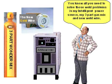
front office knows what those parameters are, so there solution is purchase a costly Pulsed MIG power source they dont need and there is always that useless three part gas MIX that the salesman will want you to try..
So you have a $2000 to $3000 dollar, regular CV. MIG power source, and you want to know about MIG Short Circuit.
During MIG short circuit weld transfer, unlike the constant open arc pulsed, globular and spray transfer weld modes, the unique short circuit arc transfer spends 50% of it's time in the "ARC Off" condition.
When the electrode positive, Short Circuit weld wire makes contact with the negative grounded work,
an "arc off" condition is generated, this condition which dramatically impacts the MIG weld energy produced.
When the MIG wire short circuits with the work, the resistance to the current in the wire drops and the weld voltage drops. With the relatively moderate slope provided in traditional CV MIG units, (power source volt amp performance output), that voltage drop, (as shown above) enables the current to rise to the slopes limit. The Short Circuit current rise will be sufficient to melt the wire tip creating another arc that forms a molten droplet. That drop is then driven into the weld pool when again the short circuit action creates slight explosive sound. This is the crackle sound we are all used to. The SC arc off, arc on cycle typically occurs in the range of 60 to 110 times per-second. When the short circuit sweet spot is attained usually around 10 o'oclock and 17 to 18 volts, the cracle sound will be at it's most rapid and constant pace..
Note: With argon gas mixes, the argon mix gas plasma (as indicated in the video below) partially covers the bottom of fluid droplet during it's formation and therefore has little influence on the weld drop formation and transfer. In contrast, when using straight CO2, the CO2 plasma formed would be UNDERNEATH the bottom of the weld droplet. Straight CO2 supports the weld drop, deterring the weld drop from detaching, this enables the drops to gets larger and then transfer in an erratic manner, (softer plopping sound) causing extensive, difficult to remove spatter.
Note the SC arc plasma formed with argon CO2 mixes.
2018. The best MIG gas mix for most weld shops is argon - 15% CO2. This is the a
MIG mix that I developed for AGA and introduced to North America more than 25 yeras ago.
UNIQUE WELD BENEFITS FROM THE SHORT CIRCUIT TRANSFER MODE:
So with that low cost, CV MIG power source you have with SC transfer, a unique weld mode is produced that provides logical weld benefits for gage applications < 4mm or any steel welds that have gaps. SC is a great MIG mode for welding rotated pipe, open root welds.
THERE IS A LOT OF INFO AT THIS SITE, HOWEVER IF YOU WANT TO BE A MIG - FLUX CORED - ADVANCED TIG OR TIP TIG WELD PROCESS CONTROL EXPERT, VISIT HERE.
I SPENT A SHORT TIME AS A WELD MANAGER AT A HARLEY PLANT AND TRIED TO BRING A LITTLE WELD REALITY TO THEIR PROCESS INEXPERIENCED MANAGERS, ENGINEERS AND SUPERVISORS. THAT WAS A LOOSING BATTLE IN A MFG N ENVIROMENT IN WHICH MANAGEMENT HAS NO CONCEPT OF WELD PROCESS OWNERSHIP.
At the Harley plant, I sat in a weld team meeting and listened to a long drawn out discussion on a robot weld spatter issue on some gas tanks. As I was new at this plant, (40 years exp.) I was asked by the plant management not to comment on the weld subjects being discussed at the meeting. I found out that the Harley "hands off" engineers and management did not understand the importance of weld process ownership. I also found out that the well paid Harley managers and engineers responsible for building the bikes were also afraid of confrontation with their shop floor personnel. The management actually believed the weld shop floor people would be sensitive to any constructive criticism of the welds being produced.At the Harley weld meeting, there were some engineers and at least six personnel from the shop floor. The discussion was how to resolve a robot, short circuit weld spatter issue on the gas tanks. After an hour, this expensive Harley weld team had not identified the root cause of the weld issue. The weld reality was the gas tank weld spatter solution required a simple weld voltage adjustment that would have taken me less than two minutes to resolve in the robot cell.
Harley and it's sad lack of Managent and Engineering
MIG process Ownership & lack of MIG weld process control expertise.
The Harley senior management believed their workers would be "sensitive" to my weld advice and my hands on involvement on the Harley shop floor. The weld reality was the workers were not sensitive to someone who knows what they are doing, however they were very sensitive to management and engineers that did not have a clue about what they daily managed.
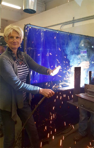
Short Circuit, Globular, Spray or Pulsed MIG, the optimun weld volt range is narrow,
and it takes less than 5 minutes to show weld pwesonnel how to control MIG weld spatter.
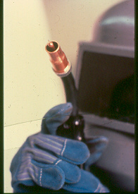
Em with her hand showing welders the spatter window
size and how to reduce the size of that window.
In training weld personnel or the few interested supervisors or managers, Em used to create a weld spatter window condition with the weld transfer mode under discussion. She would then make the weld voltage adjustments necessary to reduce that spatter window size. All the information necessary for optimum weld conditions with all MIG transfer modes are in Em's self teaching - training resources.
SC Question: Pick the most common SC volts for a steel or stainless 0.035 0.9mm wire. [a] 12 - 17 volts. [b] 13 - 19 volts. [c] 15 - 20 volts.
SC Question: If the SC weld sound is harsh andirregular the SC volts is too _______?SC Qustion: If the SC weld has small globs on the spatter tips, the weld voltage is too_____?
All answers are provided in my self teaching or training resource.
How the Harley management got themselves into a situation in which " weld process expertise or ownership", were words they would rarely use, is easy to explain. What the Harley management did not understand, was that their workers were not sensitive to "constructive" management or engineering criticism, the worker sensitivity came from many years of dealing with hands off, inexperienced front office managers and engineers that daily revealed their lack of manual and robot weld process control - best weld practice expertise.
Each year, the manual and robot global MIG weld issues, weld rework, weld rejects, weld cleaning and weld liability costs are beyond comprehension. With robots, the weld over costs are further influenced also by the too common less than optimum robot weld productivity, unnecessary hourly robot down time, the wasted man hours from fruitless plant weld team meetings, and the under utilization of the automated equipment purchased.
THE COMMON GLASS WALL BETWEEN THE FRONT OFFICE AND THE WELD SHOP?
I have been in over a thousand weld departments in more than thirteen countries, and found that in too many, the manufacturing managers and mfg. engineers had placed a "glass wall" between themselves, the weld department and the robot weld cells. The glass wall has led to the prolific lack of management and engineering weld process ownership,that has for many decades been the norm in the majority of global manufacturing plants.IF MANAGERS, ENGINEERS AND SUPERVISORS DID WHAT THEY ARE BEING PAID TO DO, THEY WOULD ENSURE THAT ANY WELD DECISION MAKERS AND THE WELDERS WOULD HAVE THE BEST WELD PRACTICES AND WELD PROCESS CONTROL TRAINING NECESSARY FOR THE PROCESSES THEY USE. THE MANAGEMENT WOULD THEN FIND OUT THAT THEIR MANUFACTURING FACILITIES DO NOT REQUIRE A WELD TEAM.
Note: A benefit of the Pulsed MIG mode for some > 18 gauge steel applications is the lower cost, easier to feed, 0.045 (1.2 mm) carbon steel or stainless wires may be used instead of the 0.035 (1 mm) wire. The 0.045 steel wire provides a little more deposition than the 0.035 wire on gauge and this may be beneficial as it allows faster weld travel rates which reduce weld burn.through potential.
I wonder in 2018, if this was what some of the frustrated
managers and engineers looked like at the CA. TESLA plant?
It would be easy task to fix the arc weld automation and weld process issues in any Tesla plant, however Elon Musk firmly believes that his weld solutions require sophisticated, costly automation and mechanical engineers with a PHD.
Elon may have a vivid imagination and billions of dollars in the bank, but the weld reality is he no different from the majority of inexperienced global mfg. managers and engineers that have their heads buried in the sand, and simply lack the process control management expertise that is essential for weld process ownership. The consequence for front office guys like this is that they typically spend their work days, developing ulcers, and run around putting out weld shop fires that result in weld rework, weld rejects and poor production.
Designers, manufacturing engineers, managers, supervisors and technicians when dealing with MIG steels or alum gage applications, will often suffer from a lack of MIG process control knowledge that takes about $300 and twenty hours to learn, this minor detail has for many companies dramatic weld cost consequences.
When robot welding thin, carbon, alloy or stainless steels on parts < 2mm, the weld decision maker may find;
[a] unacceptable part part tolerances,
[b] unacceptable weld gaps,
[c] poor part fixtures,
[d] poor weld joint designs,
[e] poor choice of weld consumables,
[f] poor performing weld equipment, especially with Pulsed MIG units.
[g] inappropriate weld parameters and poor techniques.
[h) lack of best weld practices and lack of appropriate weld mfg. instructions,
[i} lack of process control training for all involved in the front offices and shop floors.
2017: Of course the above items can lead to weld rework, weld rejects, unexpected weld costs and weld liability ramifications. The common gage steel MIG weld issues are weld burn through, distortion, and weld spatter. To add to the thin gauge steel weld issues, it's a sad fact that the majority of automotive and truck manufacturing plants that use MIG welding robots, have for decades lacked the engineering and management ability to provide the correct MIG weld process controls and best weld practice training that's essential for MIG weld resolutions and consistent process optimization with robot welds. What most of these plants will have in common is the management will get together all the persons that lack MIG process control expertise, and call them the "WELD TEAM".
I know what I say on this site will annoy some individuals, however rather than shoot the bloody messenger, perhaps it would be more effective to consider this self teaching or training resource.
APART FROM THE COMMON GLOBAL LACK WELD PROCESS EXPERTISE, ROBOT WELD MIG WELD
ISSUES HAVE FOR DECADES BEEN INFLUENCED BY POOR WELD DESIGN.

In fabrication enviroments, typically there is no one less interested in
MIG or other arc weld process controls than the
DESIGNERS
of the welded parts.
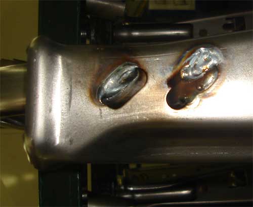
Can you provide 3 serious design flaws in these gauge, slot car seat welds.
2108: FOR THREE PLUS DECADES, WE HAD PULSED MIG POWER SOURCE WELD INSTABILITY & INCONSISTENCY ON ROBOT GAGE STL. WELDS, BUT AFTER ALL THIS TIME THERE ARE ONE OR TWO PULSED MIG UNITS WORTH BUYING..
COMMON PULSED MIG WELD INCONSISTENCY: Lets say that you are pulsed MIG welding, common thin steel parts that are 18 gage to 14 gage. The welds on the part are typically less than 2 inch < 50 mm) long. You have several robot weld cells producing the thin parts and the weld data is rarely changed in each cell, however the parts produced from each robot cell have very different looking welds. The inconsistent pulsed MIG welds could be caused by the too common lack of robot and weld equipment calibration, (managers forgot to put this in the robot purchase order), however it's also likely that this common inconsistent pulsed MIG weld issue is being generated by the pulsed MIG equip. The solution I used over the decades was to change the pulsed MIG welds to the optimum CV. MIG Short Circuit or low Spray weld settings, the same ones found in my MIG manual / robot weld process control resources.
Want to test the robot MIG process expertise in your organization?
EXAMINE THE ABOVE ROBOT MIG WELDED CAR SEAT WELDS. LETS SAY THE CARBON STEELS ARE 14 GAUGE. THIS WOULD BE A SIMPLE COMMON ROBOT WELD IN AN AUTO - TRUCK PLANT. THE MIG WELD WIRE IS AN 0.045, E70S-3, AND THE GAS IS THE COMMON ARGON 20% CO2 MIX.
WITH THE 0.045 (1.2mm) WIRE THE ROBOT TECHNICIAN COULD UTILIZE THREE WELD TRANSFER MODES, [1] SHORT CIRCUIT. [2] PULSED. [3] LOWEST SPRAY.
EACH WELD MODE PROVIDES UNIQUE PROCESS ATTRIBUTES THAT COULD BE APPLIED WITH MANY STEEL GAUGE ROBOT WELDS. IF YOU ARE A MANAGER, AT THE NEXT WELD TEAM MEETING, ASK THE MEMBERS TO WRITE DOWN THE ANSWERS TO THE FOLLOWING QUESTION.
FOR THE ABOVE ROBOT WELDS PROVIDE THE PARAMETERS FOR THE FOLLOWING.
[1] Short Circuit, Wire Feed ___ Approx, Amps____Volts____ Travei Speed_____
[2] Pulsed, Wire Feed ___ Approx, Amps____Volts____ Travei Speed_____[3] Low Spray, Wire Feed ___ Approx, Amps____Volts____ Travei Speed_____
All the information necessary (and simplified) for optimum weld conditions with all MIG transfer modes are in Em's self teaching or training resource.
UNLIKE SHORT CIRCUIT AND SPRAY, PULSED MIG IS NOT A SIMPLE PROCESS. When utilizing the pulsed MIG mode, the electronic complexity required to try and provide in a consistent, stable manner, uninterrupted, controlled pulsed weld drops over a changing short length arc gap and with the other variables that are influencing the weld transfer, some pulsed MIG equipment manufacturers know how to attain this and for decades many did not and in 2018 still don't.
And as I discuss in my Pulsed MIG Section, and in my MIG equipment Evaluation Section and also in my process self teaching / training resources, for decades the majority of pulsed MIG equipment manufactured simply did not have the capability to produce the weld MIG transfer consistency that specific welds may have required, especially with the common low parameter sheet metal welds and welds that required with short arc on times.
Note: The short weld cycle times, required with small weld lengths are common with most automotive and truck thin gage MIG welds. The weld times may often be less than 5 seconds. In that short arc on time, the robot control is telling the pulsed MIG equipment to provide three distinct sets of data. [1] Weld Start. [2] Weld
[3] Weld End and the poor pulsed MIG equipment was too often not up to the challenge.
The SC mode, video shown below, is in contrast to the Pulsed mode, a much less sophisticated weld transfer mode, that in reality could be created using a couple of car batteries,(would not be optimum, but would create a SC weld.
In contrast to pulsed, the SC process is much less influenced by arc length variations. The SC wire drives into the weld. The wire contact creates a voltage drop which on a MIG unit creates a rapid current rise that melts the tip and creates the arc that adds to the fluid weld surface. The fluid weld drop is formed and driven into the weld surface and the short circuit action occurs many times per-second. The biggest impediment to the SC welds is incorrect weld voltage, too little or too much, and current used outside the optimum SC range, (reasons for process training). Few manual or robot weld personnel are aware of the SC sweet spot weld data that is beneficial for their weld applications.
Question: Provide the optimum Short Circuit weld current for an 0.035. steel or stainless wire.
Question: What determines the SC parameter sweet spot?
My robot and manual MIG process control training programs, provide all manual and robot MIG information including of course the optimum weld start - weld end data for all Robot MIG welds..
For almost six decades, the Short Crcuit weld transfer mode available from CV. MIG equipment, if set correctly, had the potential to provide low parameter arc stability, minimum spatter with low weld burn through potential.
The above statement was reality as mentioned for many decades, however in 2018, the reality is that is if the correct pulsed MIG equipment and used correctly, then the short circuit process would be redundant.
Using Short Circuit or Pulsed. As this 30 year old Short Circuit video reveals, MIG weld process controls & best weld practice are the keys to producing minimum weld spatter..
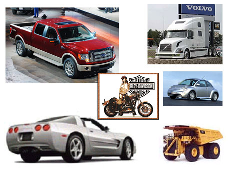
Ed now Em Craig optimized robot and manual welds for hundreds of companies in thirteen countries. A few of my robot, weld process control improvement projects.
FORD F 150 FRAMES - VOLVO TRUCK CABS - CORVETTE FRAMES- HARLEY - BIKE FRAMES - NEW VW BEETLE & MERCEDES CAR SEATS, AND ROBOT CLAD WELDS ON BOILER WALLS, ROBOTS ON PIPE LINES OIL RIGS AND THE ROBOTS WELDING THE WORLD'S LARGEST TRUCKS AT CATERPILLAR.MIG Short Circuit, Spray. Pulsed MIG, Flux Cored, Advanced TIG and TIP TIG,
numerous Fortune 500 companies have used my manual & robot
Self Teaching / Training Weld Process Control Training Programs
When an industry plays around with their prime process controls, someone needs to simpliy the process.
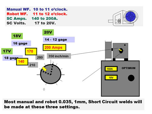
Em simplified MIG settings by developing the MIG Clock Method, this applies to all MIG and Flux Cored welds.
Em's Clock Method, Wire Feed 10 to 12 o'clock for optimum Short Circuit welds
made with 0.035 (0.9mm) Steel MIG wires and Argon CO2.
Most MIG wire feed units deliver approx. 700 - 800 inch/min. An average MIG wire feed rate of 70 inches would be provided per-wire feed clock. The above wire feeder delivers wire between the 7 and 5 o'clock positions. For an optimum Short Circuit start point, set the wire feed at 10 o'clock, and provide 17 cups of coffee, (17V). Note 10 o'clock would be the 3rd wire feed turn, 3 x 70 = 210 inch/min for your digital feeder.

E-mail. Weld Questions, 06 /20/03Hi Craig, I would like to know what the critical factors are that determine Short Circuit weld fusion. I often wonder if short circuit transfer simply won't put heat into the base metal fast enough to achieve fusion on anything greater than gauge thickness. Right now I have a single phase, Miller 185 amp power source and we use 0.035 wire. We weld steels for architectural work, balconies, railings, etc. Typically we weld 1/2 to 3/4 inch, thin, square tubes. Most of our welds appear to be in the globular mode. I don't think the Miller 185 will get me into spray transfer and am trying to decide if a 250 amp MIG power source is the solution. We are currently stuck with single phase power. What is your take on all this?
Regards, Erik Lander.
Ed's reply.
Erik, with any CV. MIG weld, the first thing the weld decision maker gives consideration to, is the compatibility of the weld mode selected with the part thickness. An 0.035 steel MIG wire requires typically 100 to 190 amps for the majority of steel short circuit welds, and over 200 amps for a Spray weld with the 0.035 wire. You could of course use an 0.030 wire to get into spray at a lower current, however wire feedability is then often a concern. Most of your MIG CV welds are Short Circuit welds, and your available 185 amps is therefore adequate for SC and 0.035 steel and stainless wires. Your concern for weld fusion with your CV MIG power source and an 0.035 wire would be on steel components that are > 4mm. For applications such as this, a 250 amp CV MIG power source would be ideal with 0.035 wires and if you want to use 0.045 wires a 350 amp unit would be logical.
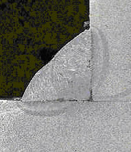
What the macro reveals with that MIG weld, is too often
the unknown scourge of the weld industry.
If every global steel MIG weld was sectioned on parts > 3 mm,
the majority would likely reveal LACK OF WELD FUSION.
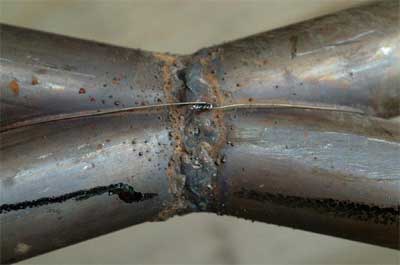
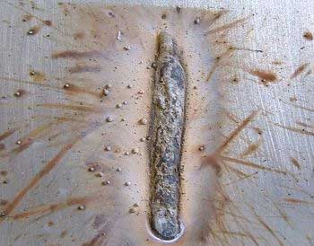
Who ever set these MIG welds does not know how to control weld spatter.
Robot and manual MIG welds can have
dramatic weld settings and best practice differences.
As robots move faster in a controlled manner and can provide controlled weld weaves, the weld decision maker will be aware that the MIG weld data recommendations can change dramatically when changing from manual to robot welds.
In contrast to manual MIG welds, when welding thin gage applications with robots, the welds typically can be made with "much higher weld travel speeds" which also allows higher weld current settings, or different weld transfer mode options. Pulsed spray transfer " typically allows robot welds to be made on carbon steel or alloy steels in the thickness range of 0.045 (> 1.2 mm) to any thickness. Robot welds using 0.035 (1mm) wire with regular "spray transfer" set at low weld start spray parameters, can be used on parts as thin as > 0.070, >1.8mm. No weld gaps and short weld lengths preferred on this thickness.
Robot welds with an 0.035 wire and short circuit can weld parts > 1 mm, under 1 mm depending on the weld joint design and tolerances, the weld burn through risks are high,
Globular Benefit: For welding those exhaust components or bike frames that are poorly put together and end up with weld gaps, an alternative weld transfer mode to pulsed and short circuit is the globular transfer mode. For globular weld transfer use 0.035 wire typically set at 400 to 600 ipm ( 1 - 3 o'clock) with a weld voltage range of 20 to 24 volts. This mode provides low to medium weld energy at higher weld deposition than short circuit, and on round parts there is little area for the weld spatter to get attached.
I wrote the Machinery Hand Book Welding Section. I also wrote the following three books.
[1] "MANUAL MIG & ROBOT WELD PROCESS CONTROL" book.
[2] "MANAGEMENT AND ENGINEERS GUIDE TO MIG" book.
[3] "MANUAL MIG & FLUX CORED PROCESS CONTROL" book.
Note: These books and my MIG self teaching / training weld process control - best practice power point programs are found in the training resources section of this site (click here). These resources, simplify the selection of optimum MIG wire feed and volt settings for all common electrode diameters used on manual and robot applications. The process control - best practice programs will provide your robot personnel and welders with the ability to instantly set the optimum MIG weld transfer modes and weld parameters for any steel application.
OVERSIZE MIG WIRES, POOR WELD CONSUMABLE CHOICES AND LACK OF WELD PROCESS CONTROL EXPERTISE ARE THE NORM IN MANY TRUCK AND CAR PLANTS:
For decades many process ignorant, auto and truck managers, supervisors and engineers, believed that when it comes to MIG welding, "the lower cost bigger MIG weld wires are more cost effective and will provide weld cost reductions" .
[] The use of oversize MIG wires for gage welds, is common in most auto = truck plants. The wires 0.045 - 0.052 - 0.062, (1.2 - 1.4 - 1.6 mm) require higher weld current than the more compatible 0.035 - 0.040 wires.
[] The use of self shielded flux cored wires is also common. Take note; These weld wires have no place in any plant in which desires consistent optimum weld quality.
[] While the majority of plants that use argon mixes utilize the E70S-6 wires. The weld reality is that the E70S-3 wires would have less oxides islands on the surface, less porosity and less undercut potential. Reducing oxides is important when welds are to be painted or coated.
To attain optimum weld transfer from the over sized diameter MIG wires requires high weld current and typically the current required will not be compatible with the gauge size welded. The bottom line is the auto industry needs managers who understand the importance of weld consumable selection, weld process controls and best weld practices.
My process control training programs both simplify and teach the best practices - process control requirements and anyone who can read English can present these programs.
MANY PLANTS WILL USE 0.045 (1.2mm) AND 0.052 (1.4mm) MIG WIRES WITH THEIR CV, SHORT CIRCUIT OR GLOBULAR MODES TO ROBOT WELD PARTS LESS THAN 0.100.THESE LARGE WIRES ARE THE FREQUENT CAUSE OF WELD BURN THROUGH, DISTORTION AND WELD REWORK ISSUES.
MANY PLANTS, ESPECIALLY AUTO / TRUCK FRAME PLANTS WILL ROBOT WELD PARTS 1 TO `4 mm AND USE AN 0.052 (1.4 mm) WIRE, YET THE SPRAY CURRENT WITH THESE WIRES IS BETTER SUITED TO WELDING PARTS > 5 mm

MIG WELD PROCESS CONTROL EXPERTISE WAS NOT A REQUIREMENT AT FORD. AS THEY DID NOT KNOW WHAT IT WAS.
AT THE INFAMOUS "QUALITY IS JOB 1" FORD FRAME PLANT IN DETROIT, ROBOT MIG WELDING ON THE TRUCK FRAMES IT WAS BAD MANUAL WELDS ON TOP OF BAD ROBOT WELDS, AND THE WHOLE THING WAS MORE OF A COMEDY SKIT THAN AN ENGINEERED, CONTROLLED FUNCTION.
THE FORD PLANT, IT'S ENGINEERS AND MANAGERS SIMPLY HAD NO UNDERSTANDING OF THE REQUIREMENTS OF ROBOT MIG WELD PROCESS CONTROLS, AND THE PLANT USED THE WRONG (OVERSIZED) MIG WIRE FOR THE TRUCK FRAME.
AT THE HEAVILY ENGINEERED FORD PLANT, YOU WOULD FIND BUCKET PERSONNEL AT THE END OF THE ROBOT LINES. THEIR JOB WAS TO USE A CHEAP SWEEPING BRUSH, DIP IT IN BUCKET CONTAINING YELLOW TYPE PAINT AND TRY TO MARK THE NUMEROUS BAD WELDS ON EACH FRAME AS THEY PASSED AT THE RATE OF ONE A MINUTE. THIS PLANT AND OTHER FORD FACILITIES HAS FOR DECADES HAD THE PROUD ENGINEERING ACHIEVEMENT OF NEVER PRODUCING A ROBOT WELDED FRAME, WITHOUT MOST WELDS REQUIRING WELD REWORK.
WHEN OVERSIZE MIG WIRES ARE UTILIZED, THESE WIRES WILL OFTEN NOT ALLOW THE USE OF THE HIGH ENERGY SPRAY MODE, WHICH FOR MOST PLANTS WAS NOT A CONSIDERATION AS THE PLANTS DID NOT KNOW WHAT SPRAY TRANSFER WAS.
OFTEN WHEN THE OVERSIZED WELD WIRES ARE USED, THEY END UP BEING USED IN THE GLOBULAR TRANSFER MODE. GLOBULAR WELD TRANSFER WAS VERY COMMON AT FORD, GM, DANA, TOWER AND MOST CHRYSLER PLANTS. THE GLOBULAR MIG WELDS WILL TYPICALLY LACK WELD FUSION, CAUSE EXCESS SPATTER AND CAUSE CONTACT TIP ISSUES RESULTING IN EXCESS WELD REWORK AND ROBOT DOWN TIME.
MIG
Optimum short circuit transfer with 0.035 (0.9mm) wires is typically found between 100 and 180 amps with a voltage range of 15 to 18 weld volts. These settings provide optimum weld results on parts < 0.100.
On the applications that utilize the 0.035 wires in the optimum short circuit current range, pulsed MIG using an 0.045 wire can also be used with similar or slightly higher weld current and deposition rates.
If plants use self shielded flux cored wires, it's an indication that the management and engineers need to look for another job, working with something that they understand.
The daily bad welds outnumber the good ones.
SELF SHIELDED FLUX CORED WIRES AND WELD PROCESS IGNORANCE
BY CHRYSLER CORPORATE WELD MANAGEMENT, CAUSED MILLIONS IN UNNECESSARY WELD COSTS FOR CHRYSLER AND IT'S SUPPLIERS.:
2006: WHEN I SEE SELF SHIELDED, (SS) FLUX CORED WIRES USED IN ROBOT CELLS, OR WITH ANY MANUAL INDOOR WELD APPLICATION, APART FROM WANTING TO THROW UP AND HOLD MY NOSE TO AVOID THE DANGEROUS AFFECTS OF THE OBNOXIOUS WELD FUMES, I ALASO WILL KNOW THE PLANT HAS NO CONCEPT OF WHAT WELD QUALITY MEANS, AND THAT THE MANAGERS AND ENGINEERS THAT APPROVED THIS WELD PROCESS SHOULD BE FIRED
At the time i wrote this, Chrysler, GM and other major auto - truck part suppliers, were utilizing the Self Shielded Flux Cored Wires for their carbon steel and galvanealed parts. This wire choice, was ironic, as these weld wires offer no weld benefits, and are the root cause of numerous weld quality, reject, rework, productivity and safety issues
The numerous annual SS weld issues wires costs corporations hundreds of millions of dollars in;
[a] HEALTH, SAFETY AND EMPLOYEE TURNOVER ISSUES.
[b] LOSS OF ROBOT AND MANUAL WELD PRODUCTIVITY.
[c] WELD PART REJECTS.
[d] WELD REWORK.
[e] WELD CLEAN UP.
[f] EVEN THE ACCEPTABLE WELDS ARE MOSTLY QUESTIONABLE.
Note: WITH THE SS WIRES, EMPLOYEE TURN OVER CAN BE HIGH AS A RESULT OF THE DANGEROUS WELD FUMES AND THEIR AFFECTS. THE BOTTOM LINE IS WORKERS WHO ARE MADE TO USE THE UNECESSARY SS WIRES, HAVE A GOOD CASE TO TAKE LEGAL ACTION. FOR MORE INFORMATION ON THE POOR CHRYSLER AND GM MANAGEMENT - ENGINEERING DECISIONS TO USE THESE WIRES, CHECK HERE HERE..
GAGE WELDS AND PULSED MIG:. In contrast to the "arc on - arc off", short circuit transfer mode, the pulsed mode is an "open arc" mode that delivers the droplets across the open arc sometimes in a consistent transfer. The consistent transfer is derived if you purchased one of the rare pulsed power sources that actually delivers the pulsed drops in a consistent manner.
In contrast to the ARC ON - ARC OFF short circuit transfer mode set at 150 amps, the pulsed mode which is an OPEN ARC mode, when set at 150 amps will deliver a weld with greater weld energy.
Note: If you were producing manual or robot short circuit welds at 180 amps and you want to try an 0.045 and the pulsed process, I would start the pulsed weld around 160 amps, then adjust.Optimum Short Circuit Transfer and Pulsed MIG Wire Diameter Selection for Gauge Applications.
CV Regular MIG Equipment. The best two MIG wirediameters for short circuit transfer are 0.035 and the rarely used 0.040 wire, (0.9 and 1.1 mm). In industrial shops, there is simply no justification for the use of smaller weld wires, and if the typical part thickness worked on does not exceed 6 mm there is no justification for larger wires...
The best MIG wire diameter for all Pulsed MIG carbon steels, stainless and aluminum gauge applications is the 0.045 (1.2 mm) wire.
When companies lack MIG weld process control expertise,it's rare that optimum weld consumables will be utilized.
WHEN WILL THEY EVER LEARN, WHEN WILL THEY EVER LEARN,
THE UNIQUE, E70S-3, (NOT THE WIDELY USED E70S-6) AND THE HARDLY UTILIZED "0.040" E70S-3 MIG WELD WIRE, ARE TWO MIG WIRES THAT THE AUTOMOTIVE WELD INDUSTRY SHOULD HAVE BEEN USING FOR AT LEAST FOUR DECADES:
Welding thin parts and using traditional MIG CV equipment or using the regular MIG modes on your inconsistent pulsed MIG equipment. if you could get your hands on the 0.040 (1.1 mm) E70S-3 wire, it would be the most practical choice for most robot and manual MIG short circuit and low current spray carbon and stainless applications on most parts that are 1.2 to 5 mm.
The 0.040 MIG wire would require less minimum spray current than the 0.045 wire which is especially beneficial for 3 - 7 mm parts, and the 0.040 wire would provide higher deposition and better feed ability than the 0.035 wires. The lack of use of this wire should be no surprise in the play around, no weld management, auto - truck industry that is short on weld process control expertise and rarely implements Best Weld Practices.
NOTE ON ATTAINING 0.040 MIG WIRES: In North America for more than two decades, Lincoln Electric has been in a monopoly position in the sales of MIG wires. Lincoln does make small quantities of the 0.040 carbon steel MIG wire, however as Lincoln typically has had a hard time keeping up with the global demand for it's traditional 0.035 - 0.045 steel MIG wires, it's understandable that Lincoln would likely not be exited about the sale of 0.040 wires.
[] The 0.040 wire, optimum short circuit current range is approx. 130 - 190 amps. This current range is well suited to all short circuit welds on the common 14 to 18 gage carbon steels - stainless applications. In contrast to the 0.035 wires, with short circuit welds and the 0.040 wires, you can expect slightly higher weld deposition rates, (faster robot weld speeds) and improved wire feed ability which can be very beneficial on robot gauge applications. The 0.040 wire needs less current to get into spray than the 0.045 wire, which makes this weld wire a wise choice for 3 to 6 mm spray transfer applications (less undercut and distortion potential).
Note: It's up to educated customers to create product demand for weld consumables that provide real world weld benefits for their weld applications..
[] If you cannot use 0.040 wire, the optimum weld wire for thin gauge current is the 0.035 wire, this wire typically uses a working weld current
of approx. 100 to 180 amps.
[] The "optimum" short circuit weld current for the 0.045 wire is approx. 170 - 200 amps. In contrast to the 0.035 or 0.040 wires, the 0.045
(1.2 mm) wire operates in a narrow, short circuit wire feed range that delivers higher weld current, thus being less suited to thin gauge parts (<2mm) and on these parts this wire will increase the weld burn-through potential.
WHAT'S BEST FOR THE WELD INDUSTRY IS TOO OFTEN LEAST UTILIZED: It's a sad weld reality that many of major companies that make MIG wires and gas mixes do not fully comprehend the weld applications and benefits or disadvantages of the weld consumables that they market. This is one of the reasons why in the last five decades, you did not see MIG weld parameter and application recommendations on that box cover of the MIG wires in your plants.
1N THE 1980s, I SIMPLIFIED MIG GAS SELECTION:
In the 1980s, while working as the Marketing and Training Manager roles with AGA Gas and later on Air Gas, I was the first person, and to this date in 2014, the only person in North America or Europe, to create optimum MIG weld parameter and application information data on labels attached to the Wire Feed Units and on the AGA MIG wire boxes sold. I also put these process control labels on the gas mix cylinders we sold. To ensure the weld shops knew what applications our gas mix were for, I made up logical gas names such as, Steel Mix - Stain Mix - Alum MIG with the Two parts gas mixes I also developed.
.
.
While we often blame China for bad manufacturing practices, read about this USA Mid West exhaust manufacturer which for years allowed it's large weld department to use the wrong MIG welding polarity.

EXHAUST WELDS, RED NECKS AND WRONG WELD POLARITY.
Question: Ed can you describe the difference that occur between Straight and Reverse Polarity in MIG welding?.
Answer: As we can all likely do with some humor in our lives, I thought, rather than answer this fundamental weld question in the traditional manner, that I would tell you about a real world welding application I was involved in a few years ago. A Midwest company that builds exhaust systems for the after market had major MIG weld quality problems with the exhausts. The absent owner of the company asked if I would visit his plant and report on the plant's weld issues. The owner told me that some of his customers were complaining that the carbon steel welded flanges were falling of the exhausts. This sometimes occurred during delivery of the exhausts to the auto parts suppliers.
I arrived at the exhaust manufacturing plant just before lunch. Like many automotive companies, the plant was too cheap to pay $7 an hour for a receptionist. I waited 30 minutes in the lobby and no one answered the phone. To get access to the plant, I walked around to the back and found an open door.
I entered the plant in the middle of the busy weld shop, and my weld senses went immediately on high alert. The "MIG weld sounds" I heard from the approx. 40 MIG weld booths were unique, but I had heard the sounds before. While thinking about the sounds I heard a grunt from behind, then again, it could also have been a pathetic sounding fart. As I slowly turned around I saw what could only be called a Englishman's nightmare, an over sized 300 lb Red Neck. As many of you are aware, Red Necks in the USA are not restricted to the south, and I was within spitting distance of the meanest looking one i had ever seen. Thankfully he just grunted, and did not ask me to squeal like a pig. However what I witnessed next was every weld managers nightmare.
THE EXHAUST MANUFACTURING COMPANY MANAGEMENT
ALLOWED THE USE OF THE WRONG WELD POLARITY
.
As I stood in the plant digesting the MIG weld arc sounds, a six foot four individual with hair growing in places I had never seen before, walked over to me. This man who had never heard of Gillette blades and he was the plant-welding supervisor, (his baby picture is shown above).
Weighing in at about 300 pounds the supervisor was covered in tatoos that must have made his mother cringe. With his stomach bulging out of the his black leather vest and a rip in his black Harley T shirt, he looked right at home in the weld shop.
The welding supervisor leaned into my face, with breath that smelt of old Budweiser, pork rinds, hot dogs, and old onions and mustard floating down his beard. He snapped, " what do want". I told him " that the owner had asked that I examine the plant's welding issues. He burped, glared and was obviously not impressed. For two minutes this man of few words informed me there were no f________ g weld issues in "his shop". It only took a short conversation with this individual to figure out that the reason he was made the plant welding supervisor, was no one in the plant could out wrestle him and no one would ever fire him.
While trying to be polite, I watched the welders and the MIG equipment used. Suspicious about the weld sounds. I noted that the ground cables on the MIG equipment were attached to the positive terminal on the MIG equipment. On walking around the weld department I noted that the "straight polarity" was being used by every welder in the plant.
Straight polarity when used in the traditional short circuit wire feed range produces a softer crackle (plopping) sound than short circuit with reverse polarity (RP). With RP the electrons travel from the cathode spots on the negative work to the positive anode on the MIG wire tip. The RP electrons impart the majority of the arc energy at the MIG wire tip, melting the wire in a consistent manner as it's fed to the work. In contrast with straight polarity the electrons travel from the wire tip to the work, with the majority of the arc energy now in the metal being welded. Straight polarity does not provide a stable arc and for most applications the lack of heat at the wire tip can cause a lack of weld fusion.
I asked the supervisor why the whole plant was using straight polarity instead of reverse. He told me that after "playing around" with the MIG equipment, the change to straight polarity reduced the weld burn through on the exhaust weld joints which had gaps.
The exhausts manufactured at this plant were so poorly built that weld gaps ranging from 3 to 6 mm were common. I politely informed the supervisor, yes I am always polite when the person I am having a welding discussion with weigh 150 pounds more than I do, that SP does reduce weld burn through with gaps. However when SP is used on the parts that don't have gaps, especially the thicker flanges which are welded to the thin exhaust pipes, the resulting welds will have insufficient weld fusion.
I also pointed out to the supervisor that the primary issue for this plant was the excessive weld gaps. I explained that it would be logical for the plant engineers and managers who were too busy to see me, to address the gap issues. Of course I also informed him that he should also switch back to RP and use the MIG equipment the way the power source designers intended. The weld supervisor with a glazed look in his eyes, muttered something about this is the way we have done always done it for the last 15 years, he turned his back on me and stomped away.
I went back to the owner and reported on the weld issues. As far as I know nothing was done because the owner was not into arm wresting and did not have the will or the people resources to address the weld gap issues. However to this day every time I see an exhaust especially one in which the flange has broke off, I have to smile at my recollection of the only plant in America that uses straight polarity.
.
Poor manual MIG weld practices
often work there way into the robot cells.


|

Inexperienced management and weld salesmanship ruined the weld industry.
A frequent Auto - Truck robot weld management solution to the robot weld problems. When they continue to have robot weld quality issues they employ more manual welders for the weld repairs. When they have robot weld productivity issues, they simply order more robots.
Weld Fact: When an unqualified manager, supervisor or engineer, asks their unqualified weld personnel, (they have weld skills without process control expertise), to evaluate a new MIG wire. gas mix or power source, is it any surprise when the incorrect weld answers are provided?
Weld Fact: At least fifty percent of the robots installed in North America are using a weld wire diameter, gas mix, power source or weld transfer mode, which impedes the weld production or the weld quality potential.
Lets see. Ed states that if we are worried about weld quality and productivity, management and engineers should take ownership and responsibility for understanding the process and weld wire selection. Boy in this company that would be a first. Perhaps it's time I got up from this computer and read his book and implemented his best practices - process control training programs.
THE TOO FREQUENT POOR RELATIONSHIP BETWEEN THE GAGE THICKNESS, THE MIG WIRE SELECTION AND THE GAS MIX UTILIZED.
-
There are 40 available argon mixes for MIG welds. The MIG gas influence on the short circuit steel weld energy should be the primary consideration in MIG gas selection.
When welding thin gauge carbon steels less than < 0.060 "weld burn through" is often a concern, especially when the welds are butt - fillet welds, or the welds are on on tubes or applications with poor weld heat distribution.
When the majority of welds are on thin < 0.060 steels, and alloy steels applications, consider a low energy, two part gas mix like an argon with 10% CO2 for carbon steels. For stainless welds use a gas mix I developed, argon - 2% CO2 . For extensive MIG gas information without sales bias, visit my MIG welding gas section.
If you MIG weld mostly gauge > 0.060 steel applications, consider a higher energy, two part gas mix like an argon mix with 15 - 20% CO2.
Note: Do not waste money on an argon - 25% CO2 mix. as this mix is not suited to spray or pulsed transfer modes.
If you use "three part gas mixes" for any carbon steels or any stainless applications, you are not using weld process logic, and typically you have been getting incorrect weld process advice from a weld salesman.
Let's see, we have another important step for weld process control. When it comes to MIG gas selection we don't need to try a different MIG gas six times a year. We don't need the advice of a gas salesman, and we should get rid of those costly, useless three part gas mixes.
The bottom line is all our steel and stainless MIG welds can be made with a couple of simple argon - CO2 mixes which are found in the MIG gas section . Holy cow, with all the money I can save, I will be able to afford that divorce lawyer.
I don't think that the following statement is something that MILLER. LINCOLN. FRONIUS, PANASONIC & ESAB would want their customers to hear.
.
"IF ALL THE GLOBAL. PULSED MIG EQUIPMENT WAS REMOVED FROM THE WELD INDUSTRY, TOMORROW, AND WELD PROCESS CONTROL TRAINING WAS PROVIDED, THERE WOULD BE NO IMPACT ON 99% OF MANUAL OR ROBOT STEELS, ALLOY STEELS MIG WELD QUALITY AND PRODUCTIVITY.
It usually takes me at least 30 minutes to prove this.
Weld skills are only a small part of the weld process.
.
.

With MIG weld process control and best practice expertise, weld quality and productivity issues should be rare when using low cost, CV MIG equipment.
With low cost CV MIG equipment, the Short Circuit, Spray or controlled Globular mode selected, can be set to produce on most steels and alloy steel applications, consistent acceptable weld fusion with minimal spatter or welds that are spatter free.
In 2014, a traditional, USA, manufactured 350 - 400 amp MIG power source would usually be in $3000 to $4000 range, while Pulsed MIG equipment would typically be in the $6000 to $12,000 range. For the weld decision maker who has to purchase weld equipment and pay the weld shop bills, it would be logical if they placed some focus on ensuring their weld personnel received MIG or FCAW process control - best practice training, This training will enable anyone in the weld shop to have the ability to fully utilize and optimize the performance of the much lower cost CV equipment.
2014. For five decades, emphasis in the weld industry has been on welding skills rather than on weld process control expertise. This is a prime reason why after fifty years, most manual MIG and FCA welders still "play around" with their weld controls, and the reason most robots never meet their weld quality or productivity potential.
IT'S TIME FOR SOMEONE IN THE WELD SHOP TO STEP UP TO THE PLATE AND FULLY COMPREHEND and CONTROL THE PROCESSES THEY OWN.
2014: Note the typical MIG wire feed control (current control) on one of the world's largest selling MIG wire feed units.
Miller, Hobart, Lincoln and ESAB have made traditional MIG wire feed controls for more than fifty years. However in 2014, not one of their wire feed controls provides information to the welder on the selection of optimum MIG weld parameters. By the way I first wrote this paragraph in the early nineteen eighties.
You can be sure each day that millions of welders around the globe are playing around with a wire feed control like the one shown, and after playing around they will end up placing a scratch or pen mark on the feeder. To stop welders playing around with their weld controls I developed a unique simple method called the Clock Method for optimum weld parameter selection.
IN THE EIGHTIES, I DEVELOPED A UNIQUE MIG / FLUX CORED PROCESS CONTROL - BEST PRACICE TRAINING METHOD CALLED THE "WELD CLOCK METHOD". THE CLOCK METHOD HAS EVOLVED OVER THREE DECADES. THE CLOCK METHOD SIMPLIFIES BOTH MANUAL AND ROBOT, OPTIMUM WELD PARAMETER SELECTION.
Ed developed the MIG Clock Method over three decades. The weld parameter Clock Method simplifies weld parameter selection for any carbon steel or stainless application and brings together the relationship between none digital and digital MIG wire feed settings, the application thickness, weld size and weld deposition rates.
The Weld Clock Method is based on the fact that traditional, global, none digital wire feeders deliver a wire feed rate of 600 to 800 in./min (15 to 20 m/min). The majority of global wire feeders have provided this wire feed range since the development of the MIG process..
Ed's Unique Weld Clock Method simplifies MIG parameter selection.
So please remember that most MIG wire feeders typically deliver approximately 700 in./min. With the ten wire feed settings, starting at 7 o'clock and finishing at 5 o'clock. Each turn on the wire feed control would therefore deliver approx. 70 inch/min per-turn. When you place the wire feed at the middle setting, 12 o'clock, this is the fifth turn. 5 x 70 = 350 inch/min.
At 10 o'clock, the Short Circuit wire feed setting delivers approx. 140 to 150 amp. This SC current is ideal for all manual carbon steel and stainless common gage sizes 0.050 - 0.060 (16 gauge) applications. At 10 o'clock, set the weld voltage at 17 volts. When training those welders, simply tell them to remember a great start point for all carbon steel and stainless sheet metal MIG welds, is 10 o'clock. with 17 cups of coffee.
To set an optimum Short Circuit weld for gage part
or a pipe open root, remember this weld start point.
Em's Method. Set the MIG wire feed at 10 o'clock with 17 cups of coffee.
USING TRADITIONAL CV AND PULSED MIG EQUIPMENT? There are 3 easy to remember, optimum wire feed settings for every MIG weld transfer mode and and 3 settings for any flux cored wire irrespective of the application. Want to learn these settings for all MIG wires?

ONCE YOU LEARN ED'S CLOCK METHOD YOU HAVE THE ABILITY TO ATTAIN OPTIMUM WELD QUALITY WITH LOW COST MIG EQUIPMENT. YOU CAN APPLY THIS UNIQUE EASY TO REMEMBER, SIMPLE APPROACH TO ALSO SET DIGITAL WIRE FEEDERS AND ROBOT WELD DATA. THIS METHOD IS USED IN ALL ED'S BOOKS, CDs AND VIDEO WELD TRAINING RESOURCES.
PANASONIC Bull S_ _ _. While Panasonic and other pulsed MIG equipment manufacturers inform their customers in the weld industry that their MIG equipment offers millions of wave form options for MIG welds, it's important that the weld shop understands that irrespective of the weld application, or the steels and alloy steels welded, with that much lower cost, more durable, CV MIG equipment, there are only three" optimum wire feed settings" required for each weld wire and weld transfer mode utilized. Its just unfortunate that the majority of weld personnel are not aware of those few optimum settings required.
.
Ed's Weld Clock Method is applicable also to all
digital feeders and robot MIG weld settings.
Any good manager, engineer or technician would strive to make things both uniform and simple in the weld shop.
Joe give me an hour to play around with the weld settings.
ROBOT TIMES, ROBOT WELD TIPS: Watch those robot "TIMES" and their influence on Robot Arc Starts - Stops and weld start - weld end size issues. At robot weld starts, it's critical for "consistent arc starts" to have the weld gas flowing before the arc is initiated. Poor arc starts occur if there is not sufficient gas, remember, its the arc plasma which is "ionized gas" which is the conductor for the electrons across an arc gap.
A robot offers many timed functions that a manual welder does not have to deal with, and robot weld time on the pendent is rarely calibrated with the actual robot times delivered.
A good thing to know if the robot timed functions are working, is use your ears. If you cannot hear the preset weld parameter changes the time allowed may simply not sufficient. For example on a weld crater fill, you may put two seconds for the crater and by rights you should put one to two volts less than the weld volts. The crater data should create a distinct crackle for the count of two seconds. If you don't hear the sound you may have to put 4 seconds into that crater data to get the two seconds of lower voltage you require.
Pre flow gas times, arc ignition times, and at the weld ends, arc delay and crater fill and post flow times. With many robots, the different arc timed functions can accumulate. The arc ignition times may combine with the gas pre-flow time which may combine with the time in which the robot examines the arc ignition before it allows the weld to commence. The accumulation of weld start function times can result in the robot being stationary too long at the weld start.
If a robot sits too long at an arc start when welding thin gauge parts, it's common to find the weld size at the weld start is twice as big as the rest of the weld. The bottom line is the with thin gauge welds only use robot times at the arc start if weld start issues occur. Arc start data becomes much more relevant on parts > 3 mm in which larger welds are required.
ROBOT MIG WELDS REQUIRE UNIQUE CONSIDERATIONS FOR WELDING GAGE APLICATIONS. MY S ROBOT BEST PRACTICES - WELD PROCESS CONTROL TRAINING RESOURCES PROVIDES ALL THE SOLUTIONS AND THE ROBOT WELD DATA NECESSARY TO OPTIMIZE THE WELD QUALITY AND PRODUCTIVITY WITH ALL ROBOT WELDS.
MIG WELDING COSTS? In many welding shops there is often greater concern for the cost of the welding wire or gas, than there is for the cost of the weld. The objective of a MIG weld decision maker should be simple. Every time the welder presses the trigger on their MIG or flux cored gun ensure the weld settings selected should deliver the desired weld quality with the wire feed control set as high as possible providing the highest deposition and therefore the lowest weld costs.
Placing focus on attainable optimum wire feed and weld deposition rates for a specific weld application, is achieved through this weld process control education.
Any MIG or flux cored wire and any weld application. Once Ed's weld process training is provided, weld quality and production objectives are fully understood and Weld Cost Calculations are Made Simple.
You can attain your complex weld cost calculation tables from your weld equipment or consumable suppliers who are typically ready to pull anything out of their hats to get your weld equipment and consumable business. Or deal in Ed's world and use a very easy method to control your weld costs.
.
Answer: Every person who has to use a wire feeder that they have never used before would benefit from the following especially if you go for a job and are required to use a wire feeder you have never seen before. Also this simple test will let you know if your wire feeder is working correctly.
[] Set your wire feed control at the "12 o'clock position"
[] Set the digital wire feeder at 350 inch/min
[] Press the gun trigger for 10 seconds you should have approximately 60 inches (1.5 m) of weld wire. Place one end of the wire under your foot and the other end should come to the top of the average size guy's chest.
2007: FEW WIRE FEEDERS WERE CREATED EQUAL. In the eighties as part of a ridiculous marketing ploy or con job, some wire feed manufacturers like Hobart sold high gear ratio, MIG wire feeders that fed the weld wire from 1000 to 1500 inch./min, (25 to 38 m/min). Other wire feeders were sold that fed much lower wire feed rates <500 ipm, (Lincoln). The low wire feed rate feeders that are commonly used for MIG welding, were designed to be used for large diameter self shielded flux cored wires. The odd ball feeders mentioned are few, yet they are out there adding to the general weld shop process confusion.
|
T
here is a reason for a MIG gun gas nozzle bore.
.
Many of the plants that I have been in that were welding gage to 1/4 (<6 mm) metals, were providing their welders with ridiculous thin, 2 to 3 mm, OD contact tips. With these under size tips (LEFT), the welders would then be made to work with gun nozzles that would have an ID of approx. 8 to 9 mm. Keep in mind in these weld shops you know all involved with the welds will be playing around with the weld controls and excess weld spatter is a way of life. With this situation, after five minutes of weld time the nozzles would be s blocked with spatter, restricting the important gas flow, or the contact tips will have shorted to the nozzle, interfering with the weld current flow. .
In one last plant I visited, the welders on the shop floor, did not seem to mind the ridiculous tip and nozzle consumables, the reason, frequently changing the tips and cleaning the nozzle was more comfortable than doing the actual welds. Of course it's logical to use a small diameter nozzles when you cannot get a standard nozzle size as shown in the right photo into the required weld space, (indication of a poor weld design).
The other amazing thing that occurs with the use of a poor weld practice like the inappropriate selection of the gun tips and nozzles. Once the weld personnel are used to using inappropriate consumables, they will then often not want to change to the correct consumables, because "this is the way we have always done it"
The primary value of a weld is based on the wages paid the employee and the costs of the weld wires and gases used. The driving factor of weld costs is weld deposition rates provided by wire feed rates and the weld current delivered through that $1 contact tip. In North America you typically have an annual cost per-welder between $40,000 and and a $60,000. Without the correct $1 contact tip to transfer the current in a stable manner and a $8 nozzle that allows the MIG gas to the weld, how much of your weld costs do you believe
Understanding the weld tools we work with and the weld deposition rate potential for our welds, now that will be a first for our weld shop. Let's face it, we either control the bloody weld process or let the process and the salesman control us.
Question. Ed where do we position the contact tip for manual or robot short circuit MIG welds?Answer.
To use the lowest voltage for thin gauge parts which typically is required for short circuit welding <16 gauge, stick the contact tip outside the nozzle 2- 3 mm. Welding short circuit on >16 gauge, place the contact tip flush with the nozzle.
Question. Ed, we short circuit 0.035 (1 mm) hydro formed gauge parts. On the seam welds, the lap joints open up between the robot fixture hold points. We always end up burning through at this area, any suggestions.
Answer:
Use a manual welder or the robot to MIG spot weld the areas subject to problems. Don't know how to set a MIG spot weld, it's in my training resources.Any manual MIG welder or robot can become a MIG spot welder. You need no special equipment, just a little technique and a little process knowledge that's found in my books. You can MIG spot weld any steel stainless, aluminum or alloy gauge applications.
Weld Question: Ed, as most of the wire feeders sold today provide a digital wire feed rate why bother with the clock method? Answer: The Clock Method "simplifies" optimum weld parameter selection and it;s extremely easy to remember any weld setting for all MIG and flux cored weld applications.
Digital or none digital when you learn the clock method you end up with the ability to instantly set any manual or automated weld without playing with the weld controls or parameters.
Please remember the traditional, low cost, more durable none digital wire feeders can last 10 to 20 years in a welding shop, and in 2007, there are over a million traditional wire feeders out there. As a weld decision maker you will most likely have to work with these common durable wire feeders. If you are a professional at your craft you should know how to set that simple one knob wire feed control, rather than "play around" with the controls. If you are a trainer this method is easy to remember, therefore it's easy to teach.
When you combine the optimum weld volts with the optimum wire feed, the optimum short circuit welding parameters will produce a crisp, consistent, rapid crackle sound.
The Sweet Sounds of MIG: Today the majority of MIG welders, use arc sounds as a method of fine tuning their weld parameters. Arc sounds are fine but they don't let you know if you are providing the required weld deposition rates.
Welders and robot operators should know "the cause of arc sounds" and the "correct weld parameter weld control response" to those arc sounds".
The weld sweet spot or sweet arc sounds attained with short circuit transfer result when the recommended optimum wire feed and voltage parameters are used. The optimum weld current (wire feed rate) and weld voltage will result in the maximum amount of short circuits achieved each second. The more rapid the short circuit crackle sound the more consistent the "spatter free" weld transfer.
The welding industry spends millions daily on cleaning welding spatter from its parts. The welding equipment manufactures even build special electronic MIG power sources designed to try to produce minimum weld spatter. The weld reality is this. For the majority of gauge applications, when welding with a low cost, durable, easy to use and easy to repair Lincoln, Miller, ESAB, or Hobart 200-400 amp, CV power source, as this 20 year old video show, set the correct short circuit or spray welding parameters and you will attain minimal weld spatter.
Weld Fact: Remember the key to minimizing short circuit weld spatter is to keep the short circuit weld drop as small as possible and create the fastest rate of short circuit weld transfer. This is achieved working in the recommended SC wire feed range, and ensuring the weld voltage is set to it's minimum. You don't need to invest in a sophisticated Fronius CMT, Lincoln STT or a Miller RMD electronic power source to control weld spatter, you simply use a traditional low cost durable, low cost CV power source and teach the welders or robot personnel to set the correct weld parameters. Most weld spatter occurs with short circuit transfer from a traditional CV power source because the welder has set their weld volts too high.
Your self taught welders may have 20 years of skills experience, however please remember "welding skills are not weld process control expertise" Instead of investing in costly, unnecessary weld equipment which may be impossible for your electricians to repair, or buying loads of anti-spatter, surely its more logical to provide your welders with some process control training.
LETS SEE WE HAVE BEEN BUYING ANTI-SPATTER COMPOUNDS FOR TEN YEARS, AND WE ARE NOW LOOKING AT VERY EXPENSIVE ELECTRONIC MIG WELD EQUIPMENT. WHY WITH A LITTLE WELD PROCESS KNOWLEDGE MY WELDERS COULD STOP PUTTING THAT COSTLY OIL AND WATER ON THE PARTS AND WITH THE MONEY I SAVE, I COULD TRY THAT MINOXIL AND GET SOME HAIR GROWING BACK ON THIS BUSY HEAD.
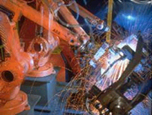
This picture proudly presented in a USA welding magazine, shows newly trained, Detroit MIG welders welding truck frames. The worst MIG welds found in the industrial world are found on in auto / truck frame plants. The excessive weld sparks seen in the picture, indicate poorly tuned manual MIG welds as evident by the fire works display. The amount of weld spatter generated is excessive and it's evident excessive wire stick outs are being used.
These welders in the photo were trained by a national auto training organization based in Detroit, it's purpose to help auto companies with their weld issues. Obviously the trainers at this Michigan organization placed little emphasis on teaching MIG weld process control.
It's a sad reality also that whenever you find bad manual MIG welds, in the same plant you are sure to find bad robot MIG welds.A Self Teaching, Weld Process Control resource for less than $400 may be the smallest investment we ever make with the largest return.
How many companies are prepared to invest a few pennies per supervisor, robot personnel or welders, for weld process control educational resources or a training program designed to optimize both the manual or robot welding in their organization?
Most of you reading this weld data will be aware that the welding personnel at your facility are not aware of all of the weld data presented at this site. I have a question for the you, how important is it to your organization to attain MIG or flux cored manual or robot weld process controls? If you think you don't need this type of weld data, do me a favor and try the MIG welding Spray Transfer quiz, and then ask your self how important is this MIG data to your organization?
Consider how easy it is with this unique clock method to bring your weld personnel into a lunch room put my CD in your lap top and project weld data that will optimize the MIG or flux cored welds. Reduce your product liability and eliminate weld rework. Get instant control of your weld costs through optimum weld deposition rates. Get your weld shop into a professional mode with management and weld personnel all walking the same path providing consistent, daily uniform weld results. Become a weld shop that frowns on individuals that play around with the process parameter controls.
HOW YOU CAN USE THE CLOCK METHOD FOR OTHER COMMON WIRES. Welding pipes or structural steels? Do you know the optimum welding parameter range settings for an 0.045 (1.2mm) Alloy Rod E71T-1 flux cored wire, for welding a 1/4 (6mm) fillet weld in the vertical up or over head positions?. What's the single optimum setting for that 1/16 (1.6 mm) flux cored wire? With the clock method its simple and of course flux cored is covered in my books.
Visit all weldreality programs.