|
|
Welcome to the world's largest web site on MIG , Flux Cored and TIG. Weld Process Controls & Best Weld Practices. To get to the root cause of Flux Cored and MIG weld issues, requires Weld Process Control - Best Practice Expertise, & some weld reality. The site provides the weld information and data required to attain the highest possible manual and automated weld quality, always at the lowest possible weld costs.This web site was first established in 1997 by Ed Craig. Contact Ed. ecraig@weldreality.com.
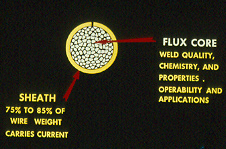
Flux
Cored Welds, part 2.
Continued from part 1:
Flux Cored Data Pipe and Plate.
GAS SHIELDED FLUX CORED:
Supporters of pulsed MIG or metal cored wires for pipe fill passes often bring up concerns about the gas shielded flux cored wires and "weld slag", however the FCA slag benefits usually outweigh the slag issues.When using the flux cored (FCAW) weld consumables recommended at this site, and those weld consumables are correctly applied, the flux cored weld slag should fall off during and after the weld. If the weld slag does not fall off, it should take only a few seconds to remove. A positive point in pipe welding is the removal of the weld slag gives the welder an opportunity to examine the weld between passes.
FLUX CORED WELD DEPOSITION RATES:
In contrast to pulsed MIG and metal cored wires for pipe welds, the flux cored slag that acts as a mold and protects for the molten metal and therefore FCA typically enables higher wire feed (deposition) rates increasing both manual and weld automation weld production potential.
Depending on the flux cored wire manufacturer's product, you can expect 8 to 12 lb/hr deposition rate for "all position" steel pipe and fabrication welds.
With any flux cored pipe or plate groove weld, always look for lack of fusion and slag entrapment in the first two passes over the root.
FLUX CORED WELD QUALITY: From a weld quality perspective, in contrast to pulsed MIG flux cored enables superior side wall weld fusion. The issues with flux cored will be trapped slag which can impare weld fusion, porosity and worm tracks.FLUX CORED AND EASE OF USE: In contrast to pulsed MIG, when the flux cored process is utilized for the pipe fill passes, the flux cored process requires much less skills which reduces training time.
If you use a "quality flux cored wire" with the correct technique and Ed's recommended parameters, and also use 300F interpass temp control with multi-pass welds, that flux cored weld slag should almost peel off as above..
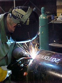
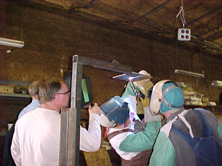
ED'S IMPERIAL OIL (Canada). COLD LAKE, PIPE PROJECT.
1990s. On above left. Ed carrying out pipe root weld research comparing MIG. STT - RMD and Short Circuit modes on a a 16 inch natural gas pipe root for Imperial Oil. On right Ed evaluating different gas shielded flux cored wires for the over head position with the Cold Lake, Canadian pipe welders, Visit this section for million dollar weld savings on large flux cored - MIG projects.
Pipe weld management is
wise when their focus is on;
[1] the pipe side wall weld fusion potential of the weld process - consumables utilized, especially with the first and second fill passes over the root,
[2] the weld personnel awareness of the optimum process control, parameter ranges and technique requirements for weld defect prevention,
[3] controlling pipe, alignment dimensions, edge preps and root gap dimensions to minimize the opportunity for pipe root weld and side wall fusion problems,
[4] the weld deposition rate potential of the weld process or consumables utilized,
[5] how easy it is to utilize the process or consumables recommended,
[6] how suitable and durable is the weld equipment selected for the shop or field work. When welding with flux cored be aware that regular, low cost CV MIG equipment will outperform inverters, multi-process power sources and pulsed MIG equipment. The CV equipment will cost less, be more durable and easier to repair.
[7] The suitability of the weld consumable selected especially for the overhead welds. In this position check the weld fluidity, ease of use and the weld transfer. Take note of the weld spatter generated in the over head position. The weld spatter can end up in the nozzle blocking either the gas flow or the contact tip bore, causing porous welds, or a wire burn back.
THOSE NARROW GROOVE PIPE BEVELS.
Sometimes in order to use a "narrow pipe bevel", the weld inspection may require "shear wave ultrasonic examination". This mode of inspection is necessary so the NDT equipment can size the weld flaw, and determine if the flaw is acceptable based on CTOD and fracture mechanic equations. Pipe line companies are aware of this complex inspection criteria and the issues generated, and therefore may only consider the narrow bevel welds or low fusion MIG modes for small pipe line projects. Narrow gap and compound pipe joints require field machining and the pipe roundness deviation is always a concern.
Note: When using narrow, bevel pipe weld joints, or weld processes such as pulsed MIG that provide minimum side wall weld fusion, extraordinary weld inspection methods may be required. What you save on the narrow weld prep is often lost on the additional weld inspection required and the consequences of that magnified inspection.
CERAMIC BACKING AND VEE GROOVE PLATE EDGE PREPS.
When making all position flux cored welds on vee groove welds on carbon steel plate with ceramic backing, two interesting questions would be, what would the minimum vee groove angle and weld gap be?
In ship yards where the typical steel thickness plate is 9 to 25 mm, when welding that vee groove with ceramic backing, the optimum root weld gap size is 5-6 mm. The minimum, "combined" vee groove angle should be 40 degrees.
THANKS TO POOR TRAINING, POOR MANAGEMENT - SUPERVISION AND LACK OF WELD PROCESS KNOWLEDGE, FITTERS IN SHIP YARDS - CONSTRUCTION PROJECTS OFTEN DON'T DELIVERS WHAT WELDERS REQUIRE.
In a ship yard, poor edge preps, oversized gaps, excess weld and extra weld rework and NDT costs can readily double the weld budget required per ship. Ed has developed a ship yard Welder Training Program so that both welders and fitters can have a greater understanding of the process requirements, the best weld practices and the weld cost and quality implications of their actions, See Ed's manual MIG and flux cored programs.
Question: Ed, in our shop when welding carbon steels we have a choice of either MIG, pulsed MIG, metal cored, self shielded flux cored, all position gas shielded or flat position flux cored wires. I would appreciate guidelines on when or where to use these processes and consumables. We weld thin gage to 1/2 (12mm).
Answer: For welding carbon steels, the following weld process logic guidelines would apply;

For all welds made in the vertical, flat, and horizontal positions, on applications less than 0.080, <2mm, traditional MIG short circuit with an 0.035 (1 mm) weld wire is well suited. With short circuit transfer (wire feed 200 to 350 ipm or 10 to 12 o'clock and voltage in the 16 to 20 volt range), the low volts / amps and arc on / arc off characteristics, provides low weld energy which reduces weld burn through potential and provides low distortion potential. Best weld position "vertical down".
Note 2006. After 20 even Miller and Lincoln have now figured out how to build decent, pulsed MIG equipment. I can now recommend pulsed MIG for most thin gage applications.
For welds on parts 0.080 to 0.150 thick, the pulsed mode with an 0.045 (1.2 mm) MIG wire can provide many benefits for all steels and especially sluggish applications like stainless or nickel alloys. However in this application range, steels and stainless are also readily welded with an 0.035 (1 mm) electrode and traditional high short circuit settings. Controlled globular transfer or low spray transfer settings with the 0.035 and 0.040 wires are also excellent.
For applications > 4 mm. In contrast to spray the pulsed process with an 0.045 wire can provide lower weld heat input for heat sensitive applications. For greater weld fusion or improved arc consistency with automated welds, consider spray.
If the steel parts have mill scale or surface contaminates that effect the MIG weld transfer, weld quality or the arc stability, it's time to consider gas shielded flux cored. Do not use the all position flux cored wires if most of the flux cored welds are made in the flat position. Use the E70T-1 wires.
Forget pulsed MIG when consistent quality, vertical up welds are required for steel or stainless >3/16, >4.8 mm, consider instead all position, E71T-1 gas shielded flux cored wires with argon 15 to 25% CO2. FCAW electrode diameters 0.035 to 0.052 (1 to 1.4 mm) are recommended. From a weldability perspective, and its weld current range and deposition potential, my first choice has always been the 0.045 (1.2 mm) E71T-1 wires.
NOTE: WHEN MANUAL CODE WELDS AND ALLOY WELDS ARE REQUIRED TIP TIG SHOULD BE THE FIRST WELD PROCESS OF CHOICE. www.tiptigusa.com
To optimize all your MIG and flux cored welds you may want to consider my book "Gas Metal Arc and Flux Cored Weld. For the book and the the most effective, CD, power point, FCAW process control training program ever developed, click.
LOGICAL FLUX CORED WIRE CHOICE: If most of your welds are made in the flat or horizontal weld positions on plate with "mill scale / rust issues" the first choice for flat / horizontal welds would be the "E70T-1" flux cored wire typically using straight CO2.
When welding on plate >5/16, >8mm, the optimum E70T-1 wire size to attain good weld puddle control with maximum weld deposition rate potential is the 1/16 (1.6 mm) wire. Avoid the larger diameter E70T-1, 3/32 (2.4 mm) and larger wires as the high current requirements for optimum weld deposition rates, typically will not be attained. Note many weld shops use the fast freeze slag E71T-1, all position flux cored wires for the flat or horizontal weld positions, be warned these wires on these applications can result in severe porosity, slag inclusions, worm tracks, poor fusion and a pock marked weld surface.
E-Mail Question:
Ed What do you think about Metal Cored and self shielded weld wires?
Ed's Reply. In my opinion, Metal Cored wires are for the majority of carbon steel applications a complete waste of time and money. As the weld benefits in contrast to solid wires are miniscule the reality is, If there were no metal cored wires available for carbon steel welds, it would have zero impact on the welding industry.
Self Shield Flux Cored above: As you can see from this picture any an insane peson or a company like Chrysler would allow self shielded wires to make welds in their weld shop.
June 19, 2003.
GMAW-P Problems on Pipe Welds:
Ed. We are trying to utilize GMAW-P on an HY-80 steel pipe welds. I was pushing for gas shielded flux cored wires, but the engineers will not allow flux cored wires for our pipe procedures. The engineers complain of poor mechanical properties from the flux cored wires on the HY metal. We can't use MIG spray as many of the welds are out of position. We are having a difficult time passing UT with our Miller Invision pulsed power source. The MIG pulsed parameters required provide a wide arc zone and long arc length, we end up with extensive, inconsistent weld fusion. We are thinking about switching to Lincoln Pulsed equipment, as they tell us with their equipment that we can get the controls we require from their unique pulsed wave forms. The Miller Equipment does not allow wave form manipulation from the interface, you have to run off the factory resets. Do you have any suggestions on getting better results with our GMAW-P equipment?
Ed's Reply: Forget that pulsed MIG equipment and especially that Lincoln pulsedwave form nonsense. Your question brings to light some of the <2003 pulsed process issues I have been talking about for more than a decade. Pulsed variable parameters and pulsed arc length sensitivity combined with a lower energy pulsed MIG arc plasma and good deposition rates combine and often result in weld quality issues. Of course to attain more weld energy with pulse one can always increase the pulse parameters and lower the trim volts, however there are optimum pulsed parameter limits and when those wire feed settings and pulsed parameters are slightly outside the optimum pulsed parameter range, you will not likely be pleased with the radiograph results.
I think you will find that wave form control which sounds great coming from the mouth of a sales rep, is going to have have little weld quality / productivity impact on your weld applications. You may want to read one of my many experiences with the Lincoln Power Wave and the ineffective wave forms when this equipment created serious weld quality (weld fusion) issues for a tier one axle manufacturer. Check out the MIG equipment section for extensive pulsed MIG issues. The real issue here is not the weld issues, its the stupidity of your engineers for not allowing the superior flux cored process to be utilized.
2008: Update from Ed: If using pulsed equipment > 2005, it's now possible to attain improved pipe weld quality, however with pulsed "manual welds" you can still expect lack of weld fusion, and from a weld quality / productivity point of view, the 2013 pulsed MIG process still cannot compete with gas shielded flux cored wires for most all position carbon steels and stainless welds.
If you want defect free pipe welds, their is only one cost effective manual process and its called the TIP TIG, (www.tiptigusa.com).
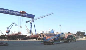
Two industries. Two Processes and Ed's Process Controls.
In the 1990s, Ed set the robot MIG welds on the above Genie products used to lift loads in the air, and in 2006 - 2007 brought "Best Flux Cored Weld Practices and Process Controls" to the Aker Philadelphia Naval Ship Yard, in the back ground..
GAS SHIELDED FLUX CORED WIRES.
FCAW. International Welding Specifications:
| Mild Steel Wires | USA |
AWS
A5.20 |
| Mild Steel Wires | Canada |
CSA
W48.6 |
| Mild Steel Wires | Japan |
JIS
Z3313 |
| Mild Steel Wires | Germany |
DIN
8559 |
| Low Alloy Steel Wires | USA |
AWS
A5.29 |
| Low Alloy Steel Wires | Canada |
CSA
W48.3-M |
| Low Alloy Steel Wires | Japan |
Z3212
- 3223 - 3241 |
| Low Alloy Steel Wires | Germany |
DIN
8575-8529 |
| Low Alloy Steel Wires | UK |
BS639-2493 |
FOR OPTIMUM STEEL- STAINLESS FLUX CORED WIRES MY PREFERENCE,
CONSIDER ESAB (ALLOY RODS) SANVIK AND KOBELCO WIRES:
| USA
E70T-1 UNS W07601 |
Flat
and Horizontal |
Canada EE4802T9 / Germany SGR1 / Japan YFW 24 |
BEST WIRE SIZE 1/16 (1.6 mm) |
| USA
E70T-2 UNS WO7602 |
Flat
position, DCEP. Gas CO2. Single pass For rusty dirty plate. Does not weld as good as E70T-1 |
Canada EE4802T2/ Germany SGR2/ Japan YFW 22 |
Use only for single layer welds |
| USA
E70T-5 UNS WO7605 |
Flat
position, DCEP. Gas CO2. Multipass Crack resistance 20 ft/lb - 20F |
Canada EE4802T5B/ Germany SGB1/ Japan YFW 24/ |
Improved CHARPY |
| USA
E71T-1 UNS WO7601 |
All
position Argon 20-25CO2 or CO2. DCEP. Multi-layers OK 20ft/lb 0F |
Canada EE4801T9/ Germany SGR1/ Japan YFW 24 |
BEST
WIRE SIZES 0.045 - 0.052 (1.2 - 1.4mm). CAN USE CO2 OR ARGON 20-25% CO2 MIXES. (MORE WELD ENERGY FROM CO2) |
With Gas shielded Flux Cored Wires:
GAS SHIELDED FLUX CORED. WORM TRACKS & POROSITY:
Weld porosity: As indicated in the picture, a cavities or discontinuities have formed in the molten weld. The porosity can be trapped inside the weld or evident at the weld surface.
Weld porosity is typically round in shape, but can also be elongated. Porosity is caused by the absorption of oxygen, nitrogen and hydrogen into the molten weld pool. The gases are then released during weld solidification. As the gases try to rise to the weld surface some gas pores will become trapped in the weld metal, some pores pass into the weld slag, while other pores will combine on the weld surface, usually in the weld center (last area to solidify) producing worm tracks.
E71T-1. Flux cored weld porosity from and Excess Gas Flow.
Copyright. Ed's CD Flux Cored Training Program
LARGE PORE WELD POROSITY. If weld surface is clean and does not look oxidized, large pore MIG / FCAW porosity is often a result of "excessive gas flow".Excessive gas flow causes weld surface turbulence. This porosity can result with gas flow greater than 45 cuft/hr. Optimum MIG and flux cored gas flow for carbon steels is 25 to 35 cuft / hr. The shielding gas flow should be measured as it exits the gun nozzle.
If the weld surface is dirty (oxidized) the cause of larger pore porosity is often a result of insufficient gas flow, less than 20 cuft /hr.
CLUSTER WELD POROSITY. A localized group of small gas pores with random distribution. Causes.
[a] Arc blow,
[b] if surface oxidized, insufficient gas,
[c] material or weld wire contamination,
[d] (low) weld parameters,
[e] welds too small or too wide and too thin.
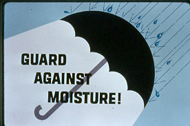
The worm holes or wagon tracks are elongated gas pores producing a herring bone appearance on a radiograph. Worm hole porosity is common in gas shielded flux cored welds when the electrodes have too much moisture in the wire flux or the weld solidifies too rapidly.
If you purchase the flux core wire from a third world or Eastern European Country, you are almost guaranteed weld problems such as severe porosity issues, and the often cheaper wire will typically provide greater the potential for Wagon Tracks especially when the weld shop you work has an either cold - damp or humid enviroment.
To reduce weld Porosity - weld Wagon Tracks,[a] extend the wire stick out as this preheats the weld wire but remember it also lowers the weld current,
[b] storing the wires in a dry environment reduces this potential,
[c] reduce weld speeds,
[d] make welds larger,
[e] avoid weaves which thin out the weld layers,
[f] increase current and decrease voltage.
The best thing you can do is order a quality weld wire as attained from Kobelco or ESAB or Sanvik.
INTERNAL SCATTERED WELD POROSITY. Weld porosity scattered randomly throughout the weld. If the MIG weld surface is gray and looks oxidized, the porosity is typically a result of insufficient gas flow. If the weld surface looks clean with scattered porosity the porosity is usually caused by the base metal part or electrode contamination, or perhaps the weld data used causes the weld to freeze too rapidly.
The above recommendations are intended to increase the weld arc energy and decrease the weld cooling rate. If the porosity issues repeat, change your flux cored wire manufacturer.
NOTE ON FILLETS AND MIG WELD ROOT POROSITY. Weld Weld root porosity frequently occurs with MIG weld fillets when using "argon oxygen" (oxidizing) > 20% CO2 mixes on parts >6 mm. With mixes containing oxygen, the oxidation potential is increased and a resulting fillet root weld is typically narrow, finger shaped. The narrow root finger area solidifies rapidly trapping the oxide reactions (porosity).
To reduce root weld porosity, change to a higher energy less oxidizing argon 10 - 15% CO2 gas mix. Increase the weld parameters, slow the weld speed, increase the weld throat thickness and avoid weld weaves. And forget about that ridiculous three part, argon - CO2 - Oxy gas mix recommended by your local gas company.
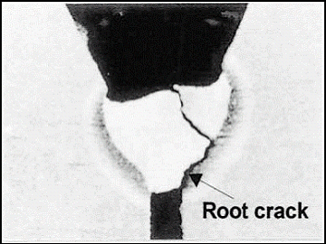
CRACKS - CRACKS - CRACKS :
There are many reasons for cracks to occur in a pipe or plate.
[] Cracks can develop from material defects.
[] Cracks can occur during the plate to pipe rolling fabrication.
[] Cold cracks can occur from hydrogen in the welds.
[] Hot cracks can occur from excess weld heat, stresses or welds and parts with low weld ductility.
[] Cracks can occur from crater defects,
[] Cracks are common from poor weld profiles susch as root beads or fill passes which are too thin, too concave or simply too weak.


Defects in the pipe or welds can grow due to fatigue during the pipe operation. In-service crack growth mechanisms include hydrogen induced cracking, stress corrosion cracking and sour service cracking.
Part of the following crack data is from GE.
Hydrogen Induced Cracking (HIC).
Sour service pipelines are vulnerable to HIC in the presence of water. The cracks can occur in pipeline steels of any strength. The HIC is typically associated with non-metallic inclusions such as elongated manganese sulfides. With x-rays or ultra sonic evaluation, the HIC in the pipe walls will appear as cracks, but near the pipe surface may appear as rough convex bumps. Acid corrosion will take place on H2O wet areas inside the pipeline and hydrogen will be produced by this corrosion reaction. In the presence of sulfides, scales on the steel surface form rather than being liberated as a gas. The atomic hydrogen diffuses into the steel, forming blisters in the microscopic voids around nonmetallic inclusions. The gas pressure in these blisters generates very high localized stress, which initiates cracking along lines of weakness in the steel. HIC develops as flat cracks in the rolling plane of the pipe material. Crack colonies develop, and failure often occurs as colonies link together in a stepwise fashion. For this reason, HIC is sometimes called stepwise cracking.
Stress-Oriented Hydrogen Induced Cracking (SOHIC).
A special form of HIC may occur when local stress concentration is high in a sour service pipeline. High stress fields can allow the hydrogen to accumulate without the need for inclusions or other interfaces. For example, some types of spiral-welded pipe exhibit highly stressed regions close to the seam weld, caused during the edge forming process. Stacked arrays of HIC can form in these regions, leading to rapid stepwise cracking failures.
Stress Corrosion Cracking (SCC).External stress corrosion cracking on high-pressure pipelines is recognized in two forms: high pH and near-neutral pH. Its believed that SCC cracks can initiate and grow in a range of conditions, including predominantly intergranular cracking in alkaline conditions and transgranular cracking in neutral pH environments. SCC can occur in a wider range of restricted aqueous environments at the pipe surface, and in extreme cases SCC has been confirmed on above-ground pipelines.
The corrosion creates crack-like features aligned at right angles to the principal stress. In most cases, the product pressure in the pipeline creates the principal stress, so the cracks are aligned parallel to the axis of the pipeline. External stresses such as ground movement can give rise to cracks at almost any angle through to fully circumferential.
The threshold for SCC crack initiation is at or about the actual yield, so in the absence of a high residual stress or an externally imposed stress, SCC is not expected in operational pipelines. However, the threshold for crack initiation is reduced by stress or pressure cycling, and in cases where pipelines experience large diurnal fluctuations, the threshold stress for crack initiation may be below the mean operating stress. Some steels show a greater susceptibility than others. On occasion, this difference in material susceptibility has been the main factor in determining where high pH SCC has become an operational problem.
Temperature is also a key factor controlling the rate of high pH SCC crack growth. If all other conditions remain unchanged, crack growth rate increases with temperature.
SCC risk can be minimized on new pipelines by careful coating selection and preservation of coating condition through the construction process. To reduce SCC risk, priority should be placed on the long-term adhesion performance of the coating and its resistance to adhesion loss from water uptake, cathodic disbonding, soil induced loading and impact or gouging.
Lap Cracks
These crack-like surface defects originate during the rolling process used to produce the plate or strip from which pipe is fabricated. Surface cracks in the hot slab become oxidized, which prevents them from welding to the adjoining metal during subsequent rolling. The cracks remain on the outer layer of the steel and are rolled over to become surface-breaking defects at a very shallow angle. They can occur in any position around the pipe.
Hook Cracks
These defects in the longitudinal weld occur during manufacture of the pipe, when inclusions at the plate edge are turned out of the plane of the steel during the welding process. They may pass the manufacturer’s initial hydrotest, but fail later due to metal fatigue. It is the turning out of the metal at the weld that gives the characteristic “hook” or “J” shape to the crack.
Girth Weld Cracks.
Although girth weld cracks can occur in
any position around the weld, they are most often found at the 6 o’clock mark inside the pipe, which is the position of maximum stress during movement of the internal clamp, when only the root bead has been made. The cracks are formed almost exclusively during construction because of inadequate fit-up and excessive stress.
Fatigue Cracks.
Metal fatigue is caused by repeated or fluctuating stresses whose maximum value is less than the tensile strength of the material. They start as minute cracks which grow steadily in reaction to pressure cycling, physical deformation of the pipeline and other mechanical stresses.
Narrow Axial External Corrosion (NAEC).
Although this is not strictly a crack, it is one of a number of defects associated with the seam weld, which are difficult to detect with standard metal loss tools because of their axial orientation. It is caused when the pipewrap “tents” over the seam weld bead, allowing moisture to enter and encouraging corrosion. The resulting loss of metal parallel to the seam can result in rupture.
Cold Cracks:
A cold crack generally occurs at temperatures blow 200F after the weld solidification is complete. These cracks can occur several days after welds are made. Cold cracks can occur in ferritic and martensitic steels such as carbon steel, low alloy steel and high alloy steels unless precautions are employed.
Cold cracks are caused by the combined effects of;[1] low ductility of the weld,
[2] residual stresses,
[3] diffusible hydrogen in the weld.Cold cracking can be prevented by focussing on these three factors.
[1] A weld's ductility may decrease with a "high carbon" equivalent and a "high cooling" rate after solidification.
[2] Residual stress in a weld can be larger than expected if the weld contains weld discontinuities such as incomplete fusion, incomplete joint penetration, overlap, undercut, slag inclusions, and weld porosity.
[3] The source of diffusible hydrogen in a weld is typically moisture in the welding consumable, the base material, the weld gas or from the atmosphere.
To reduce the potential for cold cracking:[a] Preheat the base metal to reduce the cooling speed of the weld. The preheat ensures no moisture is in the pipe. The preheat slows down the cooling rate and prevents the embrittlement of the weld and allows dissolved weld hydrogen to rise through the weld and escape to the atmosphere.
[b] Prevent weld or joint discontinuities to avoid stress build up and concentration.
[c] Use low-hydrogen type welding consumables to minimize diffusible hydrogen in the weld.
The combined use of preheating, interpass temp control and if required post heat treatment will be effective to prevent cold cracks occuring in a weld. On preheating, it is important to determine the temperature appropriate to the base metal and filler metal to be used. The appropriate temperature is generally determined for individual work by taking into account several factors such as chemical composition, restraint level, pipe or plate thickness, the weld process used, heat input, and the amount of diffusible hydrogen in the weld metal. If you dont know the preheat use 300F. If you use pre-heat then use the same temp for interpass temperature control, which ensures minimum hydrogen and minimizes grain growth. Its beneficial to wrap the weld in an insulating blanket immediately after the weld, this slows down the cooling rate and ensures no delayed cracking when the parts or vessel is cooled. Visit here for more data on Cold Cracks in Ship yards and on pipe welds.
Hot Cracks"
pass or you don'tcontrol interpass weld temperature
during mult-pass welds, watch out for those hot cracks
that will often occur in the weld center or in the weld's
HAZ.
WELD LOGIC: Limit single pass fillet welds to a max size of 5/16 (< 8 mm) and keep all multi-pass, interpass temps at a max of 350F. Avoid thin weld passes and limit weave widths to a max 5/8. Watch that weave to depth weld ratio.
Remember, there are two things that most alloys like.
[1] The highest possible weld quality.
[2] The lowest possible weld heat.
There is only one manual - auto weld process that provides this unique weld capability, this is a process i bought to North America around 2008 and at it's called, TIP TIG
For those desperate enough to use a gun with
self shielded flux cored weld wires, click here
WHEN THE WORLD'S LARGEST EARTH MOVING EQUIPMENT HAS AN ACCIDENT IT'S BOUND TO BE A BIG ONE AND IT'S LIKELY TO BE REPAIRED WITH FLUX CORED WIRES. NOW ALL I WANT TO KNOW, IS WHAT IDIOT LEFT THE DAM BULL DOZER IN FRONT OF THE BUCKETS?
Can you find the bull dozer?
THE LOGICAL WELD CONSUMABLES FOR WELD REPAIRS ON THIS TYPE OF EQUIPMENT WILL BE GAS SHIELDED FLUX CORED WIRES. ONE WELD WIRE TYPE EX1T-1, SIZE 0.045 AND THREE WELD SETTINGS COULD DO EVERY WELD ON THIS PART, DO YOU KNOW WHAT THIS DATA IS? IF NOT IT'S FOUND IN MY MIG / FLUX CORED BOOK AND IN MY CD FLUX CORED TRAINING PROGRAM.
The dozer was swept up like a toy and trapped in the wheel.
Mechanical Strength of Gas Shielded Flux Cored Electrodes.
From the ANSI/AWS Specification
AWS Classification
Tensile
ksiTensile MPa Yield
ksiYield
MpaE6XTX-X-XM
60 - 80 410 - 550 50 340 E7XTX-X-XM
70 - 90 480 - 620 58 400 E8XTX-X-XM
80 - 100 550 - 690 68 470 E9XTX-X-XM
90 - 110 620 - 760 78 540 E10XTX-K9-K9M
SEE SPEC 88 610 M means an argon mix with 75 to 80% argon balance CO2
All DCEP E71T-1 Second number 1 = all position.
E70T-1 Second number 0 = flat and horizontal position


Answer: When welding all positions, the E71T-1 "0.045" (1.2mm) is the wire of choice. The reason the 0.045 size is the wire of choice for vertical up, overhead and horizontal positions, is the all position weld parameter range of 120 to 350 amps and the high weld deposition rate potential of 6 to 17 lbs/hr. Reference the best wires. ESAB (Alloy Rods) or Kobellco would be my choice. I find these two wires provide great weldability with high deposition rate potential.
Note: Considering flux cored for robots or mechanized carriage applications? With mechanized, all position pipe welds, the welding machines can provide many benefits and advantages over manual welders. Mechanized flux cored welds will provide superior weld weave configurations, controlled weld weave frequency, controlled weave width, controlled, faster weld speeds and very important controlled Wire Stick Outs. The results will be shorter weld times and far superior weld quality than any manual welder can attain.
Answer. A good weld test on the weldability of a flux core wire is the wires ability for overhead welds on 6 - 7 mm steel plates or pipes.
A flux cored wire with stable spray (small droplet) type transfer at low parametersy is desirable. In the over head position, if at the weld parameters selected, the weld is erratic globular transfer producing excess spatter, the weld will be difficult to control. That excess weld spatter may block the contact tip bore, restricting the weld wire as it exits the contact tip.
When you want to set that flux cored wire for optimum weldability for vertical up or over head welds, there is a simple way to set the optimum weld parameters and to test the weldability of any flux cored wire, it's found in my Flux Cored Book and Process Control Program.Need more info, contact Ed at ecraig@weldreality.com, or why not get pipe welding information from two of his books, Check out this sites weld education resources. Pipe and flux cored data available in the "Management Engineers Guide to MIG" and the "MIG - Flux Cored" book.
Ed we need good weldability with high impact properties. We use a Lincoln 3/32 (2.4 mm) E70T-5 wire (CO2) welding on steels with mill scale. The intention is to attain good impact properties with tensile properties in the 90 to 100 ksi range. The welders do not like the welding characteristics or fumes generated from the Lincoln E70T-5 wire. I think we may have grind or sand blast the parts. We need good impact properties. What wire do you recommend?Answer: You pay a weldability price for using the E70T- 5, basic slag, calcium fluoride electrode. If the mechanical properties are compatible, try an Alloy Rod / ESAB E70T-1 wire called Dual Shield T-90C1 and by the way forget the 3/32 size. Use the 1/16 (1.6 mm) wire for better weldability and less weld heat input, both will improve your impact property potential. When I want a quality flux cored wire I typically will not give consideration to Lincoln products (there L50 - L56 MIG wires are good) . Also when I want quality welds those welds will be on a surface free of millscale and contaminates.
HOW GOOD ARE WELD GENERATORS AND FLUX CORED WELD WIRES?
Question: Ed. We field weld gas
and oil pipes. We weld a variety of pipe wall thickness. We like the gas shielded E71T-1 flux cored wires. With CV MIG equipment we know these wires run good. I have three questions.
[1] What about the E71T-1, gas shielded flux cored wire weld performance, when using these wires
with a CC Generator?
[2] Can I use flux cored for the roots or should I stay with EXX10 SMAW electrodes or consider pulsed MIG or short circuit for the root? With our pipe joints the root gap dimensions vary.
[3] What can I expect from the short circuit MIG welding performance for external root welds made with a generator with a CV adapter?
[1] When welding with the flux cored wires, CC generators supplied with a "CV adapter" provide great weld results Remember these wires were developed with CV MIG equipment. I tested both Lincoln and Miller generators with CV adapters. These units provided the same weld performance as traditional CV MIG equipement and superior weldability than that attained from sophisticated electronic inverters or multi-process MIG equipment.
[2] Never use flux cored for a root. For 5G pipes the external pipe root pass, is easy with MIG, STT - RMD for rotated pipes the regular low cost short circuit mode is just as good as STT - RMD. If you have the TIP TIG you have one great process for the root and fill.
Note: The SMAW / GTAW / TiP TiG processes will always be best choice for the root pass if the root or pipe dimensions vary.
ED TAKES THE STING OUT OF POOR TANK WORKMANSHIP:
Around 1992, I was hired by a company call Textron to go to Thailand and manage numerous weld repairs that were required on dozens of Stingray Tanks sold to the Thai army.
These tanks were built in Florida and due to poor weld management had serious weld fabrication issues causing extensive weld cracks. The cracks were revealed when the Thai army field tested the Tanks in Thailand.
The military vehicle defect caused a major political storm in the middle east and was a great cause of embarrassment for Textron who was and still is a major global arms supplier.
After finding the weld resolutions to the extensive weld cracks in the armor plate, I had to put a MIG and flux cored tank weld repair procedure in place for the unusual 270.000 psi, tensile armor plate. Making this application more difficult was the field weld repairs were required around the weld failures in locations high in martensite, (extremely brittle). Also to add to the weld challenge was the daily visit by Thai Generals and politicians who were concerned with the 200 plus million dollars their goverment had invested in the project.
The Thai soldiers who were allocated to do the field weld repairs had never MIG or flux cored welded. With this in mind I developed a simple weld process control program for both the MIG and flux cored process. In one week I taught the Thai soldiers how to do the necessary MIG and flux cored welds on the complex armor plates.
To make the weld repairs on the armor plates, I had ordered Miller generators with CV adapters. The adapter enabled MIG welds and the use of gas shielded flux cored wires. For the all position welds I welded the plate with Alloy Rods, E71T-1, gas shielded flux cored wires. Everything we used at the site was shipped in from the USA.
The Thai "soldier welders" were like those students you find in most third world countries, great students, open minded and untarnished by weld process ignorance, weld myths or the salesmanship you find in most industrial countries.
To understand the MIG and flux cored weld settings andto ensure they did not "play around" with their weld controls, I had the soldiers sit in a class room for two days provided the soldiers with my unique Weld Clock training method for process controls.
Note: As you can see you dont need world class training facilities to educate weld personnel on Process Controls but you do need a great program that anyone can understand and get instant weld results from.
The Thai solders and their officers soon picked up the necessary all position best practices, weld skills and the process control data necessary to always set the optimum weld parameters. An ironic weld fact, is after my MIG and flux cored process control classroom training sessions, the Thai solders now knew more about MIG and flux cored weld process controls than most global weld engineers and QC personnel. Yes that's a cow passing through the Thai weld training classroom and I can assure you there was no "Bovin Fecal Matter provided with that training program, pardon my pun, I could not help it.
[] Miller Generators with CV output,
[] Lincoln, L50 MIG wires,
[] Argon - 15% CO2, this US gas mix ideal for both MIG and flux cored. I developed this mix in the eighties for a AGA, a major US gas supplier. As for facilities, the tank welds were made in an open shed without electricity, (used generators) in the jungles of Thailand.
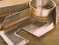
One of the tanks sub assembly.
The tank sub assembly, (shown above) had to be MIG welded. I provided the training program to solders who had never welded before. With less than one weeks training they produced the untouched part above. They used MIG spray transfer with, 0.045 wire and 85 - 15 CO2 gas on the new 270K tensile armor plate. They then used MIG short circuit welds to repair cracks in other locations. The sub assembly stiffener (above) was then welded to the tanks using all position gas shielded flux cored wires again with the same argon 15 CO2.The Thai people and welding experience was wonderful, and at the end of the day the lesson for North American manufacturers who are looking for optimum manual or robot MIG / FCAW quality and productivity.
[] You do not need highly experienced weld personnel.
[] You do not need fancy training facilities.
[] You do not require sophisticated, costly weld equipment with useless bells and whistles.
[] You do not need the advice of a weld salesman,
[] You will never need three part gas mixes or special Metal cored weld consumables.
Managers be aware that with this type of process control training, at the completion you would have welders, technicians, engineers, QC personnel who finally understand MIG and flux cored weld process controls. These individuals when using the MIG or flux cored process would not have to "play around" with their MIG or flux cored weld controls. These individuals would daily walk the same path and attain the highest possible manual weld quality and productivity from low cost weld equipment and basic consumables.
FLUX CORED APPLICATIONS, WELD WIRES, AND WELD DATA.
| Application Thickness |
Flux Cored Wire type Diameter Size | Weld Position | VOLTS + - 1 volt |
Amps + - 10% |
Wire Feed lb/hr |
Notes |
| < 1/4 <6mm |
E71T-1 0.035 (1mm) |
vertical up | 25 | 150 | 360
ipm 4.2 lb/hr |
|
| >
3/16 > 5mm |
E71T-1 0.035 (1mm) |
flat horizontal |
28 | 200 | 560
ipm 6 lb/hr |
low deposition for this application |
| < 1/4 <6 mm |
E71T-1 0.045 (1.2mm) |
vertical up | 23- 25 | 170 | 220
ipm |
too hot for < 3/16 |
| > 1/4 > 6 mm |
E71T-1 0.045 (1.2mm) |
vertical up | 24 - 26 | 200 - 250 | 300
/ 400 ipm 6-10 lb/hr |
good
choice. for pipe or bevel fill passes Pipes < 1/2 use 320 ipm. > 1/2 use 380 to 400 ipm with 24 to 27 volts |
| 3/16
to 3/8 |
E71T-1 0.045 (1.2mm) |
flat horizontal |
27- 30 | 280 > 300 |
500
- 600 ipm 7 - 13 lb/hr |
vee preps or fillet welds |
| >1/4 >6mm) |
E71T-1 0.052 1.4mm |
vertical up | 25 | 190 | 190 5.3 lb/hr |
Typically minimal weld deposition improvements for vert up, in contrast to 045 |
| >3/8 >9.5 mm |
E71T-1 0.052 (1.4mm) |
flat horizontal |
29 | 300 | 400
ipm 10.3 lb/hr |
|
| >3/8 | E71T-1 0.062 1.6mm |
vertical up | 25 | 200 | 120 5 lb/hr |
|
| >3/8 |
E71T-1 0.062 |
flat horizontal |
31 | 325 | 250
ipm |
|
| >3/8 |
E71T-1 0.062 |
flat horizontal |
31 | 325 | 250
ipm |
Note: To simplify your MIG - FCAW wire feed control settings, learn
Ed's unique, weld clock method in his books and training programs.
Ed's Answer:
Bevel 40 degree
Root gap 1/4 (6 mm).
Flux Cored Wire 0.052 (1.4 mm E71T-1.
My wire choice. Kobelco as with straight CO2 superior weld fusion than argon mixes, without the spatter and weld fumes associated with CO2 wires.
Gas straight CO2.I would use Sabaco Ceramics as I beleive they are the best avalable in North America.
Sabaco Vert Up #92A
Sabaco Horizontal 1B903H
Sabaco Flat same as Vert Up.Flat Position:
[] 6 passes including root.
[] Root weld on ceramic. WF 380 ipm - 29 V. 250 amps. Back Hand to maintain arc on none conductive ceramic.
[] Fill pass 430 ipm - 29 volts. 280 amps
[] Three cap passes designed with lower settings to avoid undercut. Use 350 ipm - 26 volts 240 amps.Horizontal Position:
[] 6 passes including root
[] Root at 260 ipm volts 25 amps 190
[] 2 passes at 320 ipm 28 vlts 240 amps
[] 3 capp passes same settings as fill.Vert Up Position:
[] Root 240 ipm 23-24 volts - 190/200 amps.
[] Hot pass 300 ipm 25 volts 220 amps.
[] Cap same as as root.
Extensive grinding of trapped slage should be applied on each weld pass, especially on the weld edges.
Question: Ed. What's the best "size" flux cored wire for horizontal fillet welds made on carbon steel plates >3/8 (> 9 mm? We use 3/32 (2.4 mm) wires.
than >5/16 (>8mm), the best size flux cored electrode for welding in the flat and horizontal positions is the 0.062 (1.6mm)
E70T-1 wire.
Many companies or weld personnel who simply don't know better will purchase LARGE diameter weld wires like the 3/32 wire. The reason the 3/32 flux cored wires are less ideal for most applications is that they require over 400 amps to produce reasonable weld deposition rates. Welders don't like working with >400 amps, and the high weld energy makes it difficult to control the weld puddle. With the 3/32 flux cored wires most welders will set "low wire feed rates". In weld reality with the large wires, welders end up producing a lot of smoke and produce welds which are difficult to control. The weld deposition rates they typically attain are usually lower than that attained with the more controllable smaller 0.062. (1.6 mm) diameter wire.
Weld Answer: The E70T-1 wire is a basic electrode that contains substantial deoxidizers. This wire provides a thick, slow cooling slag and this wire is designed to weld carbon steels in the flat and horizontal positions. The E70T-1 wire usually requires the high energy, high oxidizing CO2 gas.
In contrast to the E70T-1 wire, the E71T-1 flux cored wire is an electrode that has a rutile slag with lower de-oxidizers than the E70T-1, (deoxidizers tend to make welds more fluid). The E71T-1 wires also provides a thinner, "fast freeze" weld slag. The lower de-oxidizers (less fluid weld) and fast freeze slag help contain the molten metal when welding vertical up or over head.
The E71T-1 wire typically will use argon with 20 to 25% CO2, or straight CO2. The argon mixes are preferable for many all position E71T-1 wires, however in ship yards or for any companies that want minimal internal weld defects on parts >3/8 (> 9 mm) I recommend the Kobelco DW 50 wires which use straight CO2.
As mentioned the E71T-1 wire and an argon mix produce lower weld energy than CO2. Also the E71T-1 wire produces a fast freeze slag that will contain minimum de-oxidizers. If you have to weld on mill scale and you are welding in the flat and horizontal weld positions, the E71T-1 wires in contrast to an E70T-1 wire on mill scale applications can cause many weld issues. The E71T-1 wires when used on these applications have greater potential to produce excessive weld porosity, worm tracks, less weld fusion and inferior weld surface appearance.
|
Answer: For decades, it was my responsibility with companies like AGA, Airgas, Linde and Liquid Carbonic to test weld consumables and in my opinion the flux cored products invented by by both Alloy Rods and Kobelco are all I need.
Note about Lincoln flux cored wires: When Lincoln first brought it's all position gas shielded flux cored wires to the market, I was working with AGA (one of Lincolns biggest customers) located in Cleveland. Lincoln invited me to their facility to test their new product. I found their lower cost product had a narrow, limited weld parameter range, a lower weld deposition rate potential and the welds at the Lincoln plant ended up full of porosity. Imn sure thaey have inproved their products, but after that demo I lost my confidence in them
Note: During November, 2006 as I worked to establish best weld practices in the Aker Shipyard (Phily Naval Shipyard). I recommended that the yard use the Kobelco DW 50 (0.045) wire with straight CO2. Easy to use, no spatter, great high depsition rates and superior weld fusion to the argon CO2 flux cored wires.
Question: Ed what is the most important thing
to do when setting optimum all position, gas shielded flux cored
parameter settings?.Answer: Start your welds in the optimum weld parameter ranges as indicated in my books and CDs and be aware of how with the voltage you can set the "required minimum optimum arc length".
The arc length is the gap between the wire tip and weld.
To set the correct arc gap with gas shielded flux cored "think weld voltage". The ideal arc gap between the wire tip and weld will be approx. 0.020 to 0.030. If the arc gap is more than 0.060 the arc length may be too long spreading the weld heat over a wider area of the weld surface making it difficult to control the too fluid weld.
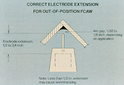
If thearc gap is to small and the flux cored weld wire is too close to the weld, you will cause short circuits of the weld transfer disrupting the weld and causing weld spatter. For the E71T-1 wire stickout use 10 to 18 mm wire stick-out. This data and much, MUCH more in my MIG / Flux Cored Book.
For vert up 3/16 to 1/4 (4.8 to 6 mm) fillet welds, start ou with 24 to 26 volts, either hold the gun steady or if required use a very slight oscillation in the weld center outwards. For vert up fillet welds larger than 6 mm the straight weave is preferred.
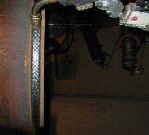
The following photo is an ABB robot I set welding a 48 inch pipe, welding vertical up. The weld wire was an Alloy Rod Dual Shield E71T-1 wire. The weld data used for the vertical up weld produced 9 lb/hr with incredible weld quality results. It took less than two hours to develop this robot weld procedure for this pipe weld.
IN 1998, ED SET THIS ABB ROBOT TO FLUX CORED WELD A 48 INCH PIPE IN THE 5G POSITION. THE WELDS WERE PERFECT AND THE SLAG FELL AS THE WELDS WERE MADE.
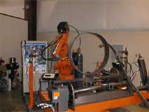
| In contrast to what many skilled pipe welders may believe, the world's best pipe welder has always been a robot. |
With this pipe fill pass welds, Four robot program points and "one weld procedure" was all that was needed to weld the fill passes in this 18 mm wall, 40 inch diameter pipe. Welding from 6 to 12 o'clock. Its amusing today twenty years after robot suitability for pipe line welds to see pipe companies using complex computerized weld controls, limited flexibility mechanized carriage equipment and multi-complex pulsed weld procedures for their automated pipe line welds.
Find
out about Ed's million dollar savings
when the Alberta
pipe welders finally switched from SMAW to Flux
Cored
For those of you who have never purchased a weld book
or process control CD, remember weld process control
knowledge will always lead to the best weld jobs.
IF YOU WANT REAL WORLD, IN-DEPTH INFO, ON THE MIG OR FLUX CORED PROCESSES, CONSIDER MY MIG - Flux Cored weld training resources
EXTENSIVE ASTM / API pipe steels / weld specification data is available in the steels program
All weld programs at www.weldreality.com.


Main Body text can go here- dummy text below
"Sed ut perspiciatis unde omnis iste natus error sit voluptatem accusantium doloremque laudantium, totam rem aperiam, eaque ipsa quae ab illo inventore veritatis et quasi architecto beatae vitae dicta sunt explicabo. Nemo enim ipsam voluptatem quia voluptas sit aspernatur aut odit aut fugit, sed quia consequuntur magni dolores eos qui ratione voluptatem sequi nesciunt. Neque porro quisquam est, qui dolorem ipsum quia dolor sit amet, consectetur, adipisci velit, sed quia non numquam eius modi tempora incidunt ut labore et dolore magnam aliquam quaerat voluptatem. Ut enim ad minima veniam, quis nostrum exercitationem ullam corporis suscipit laboriosam, nisi ut aliquid ex ea commodi consequatur? Quis autem vel eum iure reprehenderit qui in ea voluptate velit esse quam nihil molestiae consequatur, vel illum qui dolorem eum fugiat quo voluptas nulla pariatur?"
"Sed ut perspiciatis unde omnis iste natus error sit voluptatem accusantium doloremque laudantium, totam rem aperiam, eaque ipsa quae ab illo inventore veritatis et quasi architecto beatae vitae dicta sunt explicabo. Nemo enim ipsam voluptatem quia voluptas sit aspernatur aut odit aut fugit, sed quia consequuntur magni dolores eos qui ratione voluptatem sequi nesciunt. Neque porro quisquam est, qui dolorem ipsum quia dolor sit amet, consectetur, adipisci velit, sed quia non numquam eius modi tempora incidunt ut labore et dolore magnam aliquam quaerat voluptatem. Ut enim ad minima veniam, quis nostrum exercitationem ullam corporis suscipit laboriosam, nisi ut aliquid ex ea commodi consequatur? Quis autem vel eum iure reprehenderit qui in ea voluptate velit esse quam nihil molestiae consequatur, vel illum qui dolorem eum fugiat quo voluptas nulla pariatur?"
"Sed ut perspiciatis unde omnis iste natus error sit voluptatem accusantium doloremque laudantium, totam rem aperiam, eaque ipsa quae ab illo inventore veritatis et quasi architecto beatae vitae dicta sunt explicabo. Nemo enim ipsam voluptatem quia voluptas sit aspernatur aut odit aut fugit, sed quia consequuntur magni dolores eos qui ratione voluptatem sequi nesciunt. Neque porro quisquam est, qui dolorem ipsum quia dolor sit amet, consectetur, adipisci velit, sed quia non numquam eius modi tempora incidunt ut labore et dolore magnam aliquam quaerat voluptatem. Ut enim ad minima veniam, quis nostrum exercitationem ullam corporis suscipit laboriosam, nisi ut aliquid ex ea commodi consequatur? Quis autem vel eum iure reprehenderit qui in ea voluptate velit esse quam nihil molestiae consequatur, vel illum qui dolorem eum fugiat quo voluptas nulla pariatur?"