|
|
Welcome to the world's largest web site on MIG , Flux Cored and TIG. Weld Process Controls & Best Weld Practices. To get to the root cause of GMAW (MIG) & Flux Cored (FCAW) weld issues, requires Weld Process Control - Best Practice Expertise, & lots of Weld Reality. The site provides the MIG - Flux Cored and TIG weld information and data required to attain the highest possible manual and robot weld quality, always at the lowest possible weld costs.
This web site was first established in 1997 by Ed Craig. Contact Ed. ecraig@weldreality.com
When those at the top of an organization in which welding is important, don't understand what those at the bottom of the organization have to do to consistently attain manual or robot weld optimization, you have companies like Tesla, Ford, GM, Chrysler, Honda, Toyota, and any other organization in which management has not figured out how to attain ownership of their simple to control arc welding processes.
2018. I wonder if Elon Musk of Spacex ever wondered about his illogical ability to manage to build space ships, and yet struggles daily to put simple robot steel welds on his Tesla cars, (I know the reasons, see Tesla below).
When any company allow the common weld management "lack of process ownership", with the "play around" with weld controls weld shop culture, to infiltrate a robot cell, you should know the robot cell will rarely attain consistent, optimum weld quality, with the highest robot weld production efficiency.
Being aware of manual weld shop issues, help resolve robot weld issues.
As long as the manual welders were making smoke and
sparks, management accepted the results
THE WELD SHOP VERSUS MACHINE SHOP LOGIC: Have you ever thought about the contrast from a well run machine shop, to what goes on in the typical fabricating weld department that uses MIG or flux cored welds. In the same facility, over in the machine shop, the machinist will use their process expertise to finely tune their lathes or milling machines, while for decades, in the global weld shops you will find that the majority of welders will "play around" with their weld controls. These are weld controls that in reality require no more than four simple weld settings for the weld wire utilized. By the way these are also MIG power source weld controls that have hardly changed since the 1950s. And to add to the weld shop issues, the welders will then use their self taught, mostly incorrect, manual weld techniques and weld practices to make the welds.
WELD MANAGEMENT & FRONT OFFICE APATHY: From either a manufacturing or engineering perspective, the front office weld decision makers are usually involved in the part design, (often poor from a weld perspective). They will also provide the materials, process requirements, and perhaps too often, inadequate or poor weld procedures. Also when new weld equipment and consumables are required, the front office personnel will do what they do well, they pick up their cell phone and request advice from the local weld sales-rep. This is often a sales or tech rep that rarely will have have an weld shop experience.BEING AWARE OF THE ROOT CAUSES OF ROBOT WELD ISSUES IS AN IMPORTANT STEP IN ENABLING WELD DECISION MAKERS TO HELP PREVENT WELD QUALITY AND PRODUCTIVITY PROBLEMS:
THE WELD ROBOTS ARRIVE: When robots are added to the traditional global weld shop culture or to a fabrication. department, the robots instantly will offer a new weld process complexity that quickly reveals the weld lack of weld process controls - best practice process expertise short comings that for decades have been prevalent both in the weld shop and in the front office.
THE IMPORTANCE OF WELD PROCESS EXPERTISE AND WELD PROCESS - EQUIP OWNERSHIP:
To make the blind robots attain the highest possible weld quality and productivity, management will most often have inexperienced, supervisors, robot technicians, maintenance personnel, weld inspectors and engineers forever playing around with the robot settings, that is when they are not busy trying to quench the daily weld shop fires.
By the way, most global, honest mechanical or weld engineers will tell you that their educational institutions did not provide the weld process control - best weld practice expertise education that is available to them at this site. Expertise that instantly positively impacts any robot or manual arc weld application.
For those that have an open mind, sense of humor & the thick skin required to run a weld shop, welcome to robot weld management requirements, and robot weld tips.
FEW ENGINEERS OR TECHNICIANS IN AUTO / TRUCK PLANTS WILL HAVE THE EXPERTISE TO INSTANTLY PROVIDE THE CORRECT PROCESS RESPONSE TO THEIR DAILY ROBOT MIG WELD ISSUES?
ROBOT WELD PROBLEMS?
The solution for many companies is have a weld team meeting in which
the inexperienced weld decision makers provide advice to the inexperienced team.
FUNDAMENTAL ROBOT WELD QUESTION:
Using argon 10 - 20% CO2 mix with an 0.045 (1.2mm) E70S-3 wire, provide an optimum. start point of spray transfer which would be suited to weld a 3/16 fillet. Provide the robot wire feed setting, voltage, travel rate. The robot has 30 minute arc on time, how much weld wire will be used?.
FUNDAMENTAL ROBOT WELD QUESTION:
There is a blob formed on the end of the 0.045 MIG wire after each robot weld. This blob is oxidized and is likely the cause of the poor arc starts. What is the cause of the blob and what is a simple robot solution?
FUNDAMENTAL ROBOT WELD QUESTION:
You are using a 70S-6 wire and it's causing paint issues, why?
20108: As we are aware, that dumb arc welding robot is however a complex multi-axis, computerized controlled machine that can enable superior control and manipulation of the weld gun. However if the process is poorly understood by humans the robot will be in the same ball park, and the reality over the last three decades, is its the "minority" of global weld robots that will consistently attain their weld quality or weld production potential.
Apart from the human short comings, there are many other reasons that will impact the robot weld quality and efficiency. Poor part and fixture design are the norm. The lack of ability for mechanical engineers to provide parts with the dimensions specified. The use of poorly suited weld consumables, and of course for decades we have had poor performing inverter MIG power sources.
A COMMON FRONT OFFICE DISEASE, IS CALLED LACK OF WELD PROCESS OWNERSHIP.
In most auto- truck plants where welding robots are in abundance it's not unusual to find dozens of highly paid engineers dispersed throughout the plant's offices. Many of the engineers will spend much of the day sitting in front of their computers, or perhaps they like to take an occasional 15 minute walk around the facility with a clip board under their arm. Then as it happens daily, all hell breaks loose, the robot weld lines have ground to a halt due to some weld problem. Alarms sound throughout the plant, management reach for their Tums, and many of the engineers will do what they do best, faster than Wyatt Earp could draw his gun, the engineers reach for their cell phones to try and make contact with the under trained, lower paid robot technician who will rush over to play around with the weld settings or simply provide a band aid fix for the robot weld issue. While funny, this is unfortunately too common in most weld departments throughout the auto industry, and it's also a reflection of inexperienced management.LACK OF WELD PROCESS ENGINEERING OWNERSHIP, SIMPLY MEANS LACK OF MANAGEMENT.
ENGINEERING AS DEFINED BY WEBSTER'S DICTIONARY."The application" of scientific principles to practical ends." It's a pity today that with arc welding robots or even manual welds, that we see few engineers applying the "APPLICATION" of scientific / engineering principles to welding. In contrast, we do see too many engineers avoiding their process responsibility and taking far too much advice from weld salesmen.
SOME OF A WELD MANUFACTURING ENGINEER'S RESPONSIBILITY.
BE ABLE TO ADVISE ON SAFETY, DESIGN, AND PART WELDABILITY.
ENSURE PART SPECIFICATION DIMENSIONS AND PART CLEANLINESS IS MAINTAINED.
UNDERSTAND THE CONTROLS REQUIRED FOR THE WELD PROCESSES UTILIZED,
UNDERSTAND HOW TO CONSUATENTLY ACHIEVE OPTIMUM WELD QUALITY WITH ROBOTS.UNDERSTAND THE REQUIREMENTS TO CONSISTENTLY ATTAIN MAX. ROBOT PRODUCTIVITY.
UNDERSTAND AND BE ABLE TO MINIMIZE AND CONTROL WELD COSTS.
UNDERSTAND THE PARTS RISK ASSESMENT & LIABILITY CONCERNS.
UNDERSTAND THE TRAINING METHODS REQUIRED FOR THE WELDS.
When any vehicle is involved in a collision and life is put at risk, one would hope that the vehicle provides the protection in accordance with the designer's structural and weld specifications. (a rare event for most auto - truck mfgs,)
When mfg. practices and welding processes are utilized in the construction of a vehicle, and the welds are not made in accordance with the design, (common event) the resulting poor quality welds and the weld repairs (extra weld heat on HS steels) will typically produce a negative influence on the vehicle's structural integrity.
You would think with the ever increasing legal awareness of the global poor weld mfg. practices, along with the resulting liability consequence and costs. that a red light would start to blink in some managers office?
Same robot weld data applied to 4 of the same robots,
the results, different weld parameters delivered.
PANASONIC POWER SOURCES FROM MY EXPERIENCE WERE ONE OF THE WORST.
AROUND 2004, AND FOR MANY YEARS AFTER THE WORST INVERTER MIG EQUIPMENT THAT I WORKED WITH IN NORTH AMERICA, WAS USUALLY MADE BY PANASONIC, MOTOMAN, LINCOLN, MILLER AND ESAB. AS A MATTER OF INTEREST THERE WAS ONLY ONE COMPANY AT THIS TIME THAT WAS SELLING PULSED MIG EQUIPMENT THAT ACTUALLY PERFORMED WELL. THAT WAS OTC,
HONDA AND MIG WELD HELL: After he purchased my robot weld process self teaching program, I became friends with one robot weld manager who worked at Honda. At his plant. he was responsible for more than 200 MIG robots. The managers life was a constant fireman while he daily struggled with numerous, never resolved weld issue that came from the Panasonic power sources that were purchased with the Japanese robots. In our frequent discussions I had told him that for many years i was well aware of the Panasonic equipment issues that he had to work with. The weld reality was the Panasonic MIG power source was the most illogical, inconsistent, erratic weld equipment that had ever landed in North American plants.In the many factories that I was asked to resolve robot weld issues, I used to squirm when I saw any Japanese weld equipment, and especially the Panasonic or Motoman pulsed MIG equipment. With this equipment and the Miller - Lincoln inverters I knew that in many cases the weld issues in the plants could be slightly improved but not fully optimized till that weld equipment was replaced.
In 2004, as the Panasonic robots and their MIG equipment was common in the Japanese car plants in North America, I thought that while at the AWS reality show, that I would spend some time evaluating what the new Panasonic Pana Star AA2 - AA11- 350 and the HM 500 power sources had to offer.
PANASONIC BOVINE FECAL MATTER AT THE WELD REALITY SHOW:
At the AWS Panasonic booth, a Panasonic sales rep in his twenties, was keen to provide me with weld process advice and sales induced revelations about his companies Panasonic MIG equipment. He also wanted to educate me on Japan's concerns for weld penetration. Now If you are new to this web site please keep in mind, at that time at the show, I had been involved with MIG process evaluation and optimization for approx. 40 plus years, (as I edit this web page it's 14 years later and I am still working on process improvements. This brainwashed child was dead keen on trying to influence me on why his companies power source should be used with either manual or robot steel welds.
The Panasonic sales-rep provides his sales pitch at the AWS show,
"Ed (before Em), this new Dip Pulsed MIG power source is really unique as it provides "Artificial Intelligence". The rep continues. "That one of the things that effects pulsed weld penetration is when the pulsed arc length changes, as the arc length is shortened the pulsed drop may not be allowed to form without a short circuit interruption, this therefore effects the pulsed arc stability and consistency of the weld fusion attained"The poor sales rep did not realize that the problem he described had been a major issue especially with with his companies equipment since it was introduced into the USA. He also did not realize that his AI weld equipment that sat proudly on display at the weld show, would reveal when I evaluated it, that it still could not provide a consistent, stable pulsed weld transfer, and that the issues were further intensified with short weld cycle times. Yes I am aware that today in 2018, electronics evolve, however this simply shows you more evidence why some companies should stick to making televisions rather than designing weld equipment. I did not try to educate the kid as I like his enthusiasm and he would have a good career in weld sales where BS is a great attribute.
Today as I write this in 2018 after close to 40 years since their development, most mid priced range ($6000 to $10,000 Pulsed MIG equipment offers limited weld benefits and many issues for steel and low alloy steel welds. However inverter pulsed equipment is now a way of life in robot cells. And as I found out this week in two Genesis cells that have the Lincoln PowerWaves the pulsed MIG modes are still causing arc instability and crater issues and the pulsed mode continues to add weld process confusion for the robot programmers who have not been trained in process controls.
BILL AN UNUSUAL CORPORATE VP WITH A RARE WELD MFG. POINT OF VIEW, CONTINUES WITH A FEW WORDS OF WISDOM. "JOE, THE SHAME IN THIS COMPANY IS IN THE LACK OF EFFORT BY OUR FRONT OFFICE WORKERS TO LEARN THE WELD PROCESS EXPERTISE - BEST WELD PRACTICES NECESSARY FOR ROBOT WELD OPTIMIZATION".
VP BILL continues; "Joe when quality / productivity issues happen in the robot cells, I don't want to see a report or hear about what those workers on the third shift did. What I want to know, is why our managers, engineers and supervisors are allowing the issues to happen and what are they doing to resolve them".VP BILL is in fine form. "Another thing Joe, lack of front office robot MIG weld accountability - ownership is too common in all our plants and unfortunately according to what I read on weldreality.com, this is also a bloody global mfg. issue. Joe, I want you to be aware that there is no shame in our white collar general lack of weld process control - best practice engineering knowledge, I know they don't teach this stuff to graduate engineers, however from my perspective, there is great shame when our plant managers, engineers, supervisors and technicians are aware that they lack weld process control - best weld practice expertise, and they don't do anything about it".
VP BILL. "The bottom line Joe is this. I no longer want to see our key managers - engineers - supervisors getting weld advice from some bloody sales-rep with a degree in history, by the way a rep who likely has never managed a weld shop.
REMEMBER WELD SHOP CHANGE TYPICALLY REQUIRE CONSTRUCTIVE
CRITISISM, SO PLEASE DON'T SHOOT THE BLOODY MESSANGER.
The purpose of this section is too hopefully provide a catalyst that will enable robot weld decision makers and managers to provide the weld engineering and weld shop changes that for decades have been necessary, especially in many global auto / truck mfg. facilities.
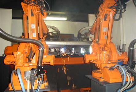
Welcome this is Ed, now thankfully Emily Craig. It pleases me sometimes when I am out in my car, and I view a few of the weld projects that I provided robot MIG weld quality and weld productivity improvements, (photos below).
A few of the robot projects that I was
asked to improve the weld quality and productivity.
From Submarines to the Mars Orion Space Craft, from Ships to the American Icon products above. For Emily the weld applications were not that relevant, as optimum quality welds would always be provided through weld process controls and the use of logical best weld practices.
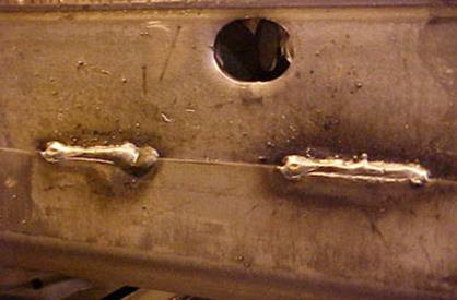
Just another another day at a truck plant
making another WELD MESSHow many managers - supervisors - engineers or technicians would walk past the above FRAME manual MIG weld repairs, and instantly recognize there were serious manual and robot MIG weld process quality, productivity and cost issues going on?
By the way the above manual MIG welders had just been trained for Ford by a major welder training organization selected by Ford in Detroit. From my perspective Ford simply paid for the bind to lead the blind.
Lincoln Power Wave and it seems like never ending pulsed MIG issues.
I think it started around 2000, and here we are in 2018 and I am sill dealing with the Lincoln PowerWave, aluminum and steel EXCESS WELD END CRATERS AND WELD CRACK ISSUES in robot weld cells. Yes its the older version of the PowerWave but it frustrates me that i have to fix issues generated by Lincoln, power source issues that have cost my client hundreds of thousands of dollars, issues that Lincoln never took ownership of.
If you want to make your weld manufacturing life more expensive, more complex, and create more weld rework and rejects when it comes to selecting the power source for your robot cells, you would listen to a salesman or the robot intergrater who, may be process biased or process ignorant.See PowerWave and Ford Axles and Truck frames.
Lincoln PowerWave, robot MIG welds and Ford 150 Truck Frames.
I was invited to this USA tier one supplier to provide weld resolutions for the world's best selling truck frames. I found six major issues that were effecting the Ford robot frame "pulsed MIG welds"
The welds were made with an 0.052 (1.4 mm), (wrong choice) MIG wire and a Lincoln Power Wave. (poor choice). Can you look at some of the frame welds below and identify the root cause of the issues?
Could you instantly provide the data to correct and recommendations to resolve these sad frame welds. All the process control data you need for optimum robot weld quality and productivity for any application is available in my low cost, CD training programs.Most often lack of weld process control expertise is missing in the majority of robot cells, and also the poor choice of the power source and consumables selected plays has a great influence.
World's biggest selling trucks and the too common lack of
management - engineering robot weld process control expertise.
When so called sophisticated MIG power sources are used with robots, and
the company lacks weld process expertise, above is the norm.
In robot cells, "WELD TIMES" are often the cause of robot weld start and weld end issues.
At weld starts, depending on the welds you may benefit from an arc ignition time to attain consistent arc ignition. However when robot welding SMALL fillet or butt welds < 3/16 (< 5 mm) in size, it's will often beneficial to zero the arc Ignition Delay Times" and get the gas pre flow started with a flying arc start.
A robot ignition delay time in combination with a pre flow gas time may create too much of an arc ignition pause. The pause may lead to a larger than required weld usually in the first 1/4 of the weld at the start, (photo above). Remember the times put into that robot program our rarely accurate and can be much higher or lower than the programmer expects.
For two decades the interface robot to power source timing issues have been an issue with most robots and needs more consideration from both the robot / MIG equipment manufacturers.
Some robot manufactures believe their robots will provide the controls necessary for the weld starts (poor starts) and stops, (crater issues) while in contrast the MIG equipment manufactures believe their power source should provide these controls, it's been this way for two decades, Ying versus Yang, and screw the weld shop.
In contrast with larger welds as typical on parts > 1/4, a longer the arc start / end times and pre-gas - post-gas flow times are required. To establish the weld puddle with welds larger than 1/4, an ignition delay real time of 0.3 to 1 second is normal. At the weld end you typically want to use the same or slightly lower wire feed rate as weld with a 1-2 volt decrease. The voltage decrease reduces the energy to reduce the ball size on the end of wire, and the the lower weld energy enables a convex crater to form. The burn back should be adjusted so that the wire is about 3/16 to a 1/4 from the end of the contact tip. The crater fill and burn back typically requires 2 - 5 seconds of post flow gas to protect the weld end and reduce the potential for oxide formation on the wire tip. (oxides on wire tip at weld ends influence robot arc starts). By the way if you cannot hear the start - end time data changes in the weld data, the times you programmed into those welds are ineffective.
Aluminium welds require long start delays, this is necessary to break up the aluminium surface oxides.
Note. In robot cells, often at weld starts, the most troublesome robot weld is often the very first weld, or a weld made after a long weld pause. The problem occurs because the welding wire is "cold", electrons travel better when the wire is hot. For this situation you may benefit from using a shorter wire stick out at these program points. Always have a least 2 robot arc re-strikes programmed for all welds.
Optimum Robot Spray Start Data for carbon steels with 0.035 (1mm) wire welds on parts > 4 mm. For the 0.035 spray weld arc start, set the wire feed at 500 in./min with 27 to 30 volts. This recommendation purposely utilizes low spray transfer wire feed rates, settings which require "minimum spray volts". The low wire feed rate and moderate (not too high) voltage is the best combination for weld start data. This weld data not only provides optimum arc starts it also reduces the potential for wire burn backs to the tip at the arc starts.
There are many factors that influence robot weld profiles at arc starts and at arc ends and these with the resolutions are addressed in all my robot weld process training self teaching and Training resources.
.
It was just another frustrating weld application using the Lincoln PowerWave, we had robot pulsed MIG weld cracks - undercut - and excess weld end craters on the Ford truck axles.
ROBOT MIG WELDS AND A MILLION AXLES A YEAR FOR FORD:
Around 1999: My weld task appeared simple. American Axle a Michigan Tier One, manufacture, ordered two robot systems to weld the truck axles.
I was the weld manager for ABB Robots and responsible for the weld processes. When the robot cells were complete, ABB was required to provide approx. 5000 welded axles as part of the robot cell run off.
American Axle had previously utilized the traditional Lincoln CV. 400 to 600 amp MIG units. The CV MIG equipment using the spray transfer mode had never created any serious weld quality or productivity issues in the past. The weld engineer at the axle manufacturer was influenced by Lincoln's equip. advice and was responsible for the selection of the Lincoln pulsed PowerWave weld MIG equipment.
Note: The carbon steel, MIG wire selected by the axle manufacturer was 0.052 (1.4mm).
Two factors were critical for the axle pulsed weld project:[1] The surface axle fillet weld sizes must never be smaller than a 1/4 (6mm).
[2] As the annual axle production was a million plus units, every second used in the robot weld cycle time was considered highly critical.
TRADITIONAL AXLE WELD METHOD: The axle manufacture had produced axles for decades. With the regular MIG CV equipment. The axles were welded with an 0.052 (1.4mm) MIG wire and an argon - CO2 mix. The CV. MIG. equipment used Spray transfer to weld the 1/4 (6mm) fillet welds. Robot weld travel speeds of 20 to 22 in./min were typical. My first objective with the Lincoln PowerWave and it's pulsed mode with the 0.052 wire, was to try to attain the same travel (production) rates as that previously attained.PULSED AND DEPOSITION RATES: When setting the Lincoln PowerWave PULSED weld data, to attain the desired weld speeds as the CV welds, I had to set the 0.052 (1.4mm) pulsed wire feed rate at approx. 420 in./min. This wire feed rate is considered the high end of traditional Spray transfer for an 0.052 wire.
NOTE: For decades with regular MIG spray transfer and the traditional low cost CV MIG equipment, a MIG wire feed rate of 420 inch/min was used with the 0.052 (1.4 mm) carbon steel MIG wires. This procedure had been used by American axle successfully for many years. This traditional CV MIG weld equipment, sells in the USA for $3000 to $4000. The equipment was durable and successful and had hardly changed in four decades.
The Lincoln PowerWave Pulsed Mode, caused the weld cracks in the axles:
It was evident when I was setting the Lincoln Power Wave at the WF of 420 ipm, that the pulsed mode did not respond well to the 0.052 wire. The resulting high energy, pulsed arc plasma produced was both "narrow and intense" . This resulted in a weld arc plasma that caused a "deep penetrating (digging) effect" on the axle welds.
Note: High wire feed pulsed settings require very high peak current that excites the plasma..
The first big news that came from the high Power Wave pulsed settings, was with the robot weld travel rates attained. At a weld speeds of 20-22 inch/min, I ended up with an external fillet weld profile that measured only 3/16 (4.8mm). When the 3/16 fillet welds were cut and a macro evaluation of the internal weld profile provided, it revealed that the intense, narrow pulsed plasma had caused the weld to penetrate almost threes times greater than traditional MIG spray penetration, so we ended up with a smaller, visible surface weld profile.
As we were at the maximum wire feed rates, to get the deep penetrating, undersize fillet weld to an acceptable 1/4 fillet weld size, the robot, pulsed weld travel rate would have to be reduced to a travel rate of 15 - 17 in./min.
The 25% reduction in the robot weld travel rate would have a huge impact on the axle weld cycle time, remember every second lost was multiplied by a million axles. To see if I could modify the PowerWave pulsed settings, I went through all the possible external Power Wave pulsed parameter adjustments. No matter what I did with the parameters. at the WF. 420 ipm I could not change the pulsed plasma intensity / profile or agitated, excess energy pulsed drops . Knowing the response I would receive by the Lincoln people I reluctantly contacted their head office. The reason I was reluctant to contact Lincoln, was with this company I had experienced decades of of BS.
As this was a major Ford project, Lincoln responded and flew in one what they thought was one of their brighter weld engineers. The engineer arrived with his laptop in tow. It's a sad state of affairs when to try and fix a weld someone believes they need a computer.
I demonstrated to the young inexperienced Lincoln engineer how at the required 420 inch/min wire feed rate, the resulting pulsed plasma from the PowerWave was too narrow and too intense for the thick wall steel axle application, "a problem Lincoln should have already been aware of".
The Lincoln engineer, who simply did not understand fundamental arc physic, assured this old fart that one of the prime features of the PowerWave was that with the assistance of his unique magic lap top software, he could change the power source wave forms to lower the energy from the electrons. Being a gentle soul I smiled at him, and said "good luck son".
To perform the robot test pulsed welds, I provided the Lincoln engineer with a long piece of 3/8 (9 mm) carbon steel plate. I had the plate surface ground. I let the engineer know that when his power source could place a robot weld on the surface of this 3/8 plate using the 0.052 wire at 420 inch/min without providing an unacceptable digging crater at the weld ends and undercut, then his work was done.
The red faced frustrated Lincoln rep. no longer smiling, folded his computer and left. He did make the usual promise that Lincoln employees make when they know the fault is theirs, he told me that "his people" would look into the situation and get right back to us.
Over the years, when dealing with numerous induced Lincoln weld issues I had heard this "we will get back to you" Lincoln canned response many times. Of course his people never got back to us. Lets face it, a duck is always a duck and BS is always BS.
I had hoped while he was trying to set those pulsed welds, that the young Lincolnengineer had absorbed a weld fact that I had known while he was still in his mothers womb. Pulsed weld equipment can offer millions of wave forms, however as with all weld transfer modes the pulsed mode provides a limited optimum wire feed / weld parameter range for the specific wire diameter utilized.
Irrespective of the potential wave form configurations from a power source, there are only so many electrons that can be squeezed into the plasma generated across the MIG arc. Also to attain optimum weld fusion on a specific steel thickness, the weld wire size and wire feed rate must provide a specific voltage, current and weld travel rate. This is of course a fundamental weld fact, however the wave form ~~~ crowd ~~~ often will place more faith in wave forms than they do with weld logic.
Note: To find out how these welds led to thousands of weld cracks in the ford axles, visit my Pulsed MIG Program. I did inform the American Axle management and sent a letter to the Ford legal department, both took no action.
Finally I found an automated weld application
that benefited from Pulsed MIG welds

A condensed review of one of my automated
weld report on Catalytic Convertor parts.
So it was around 2004 and off to Florida, not to visit the beach but to assist a company that produced among other things torque converters. The primary issue I found with the automated, Bancroft MIG welded, stainless Torque Converter parts was the 0.053 thickness and the wide gaps. On MIG welded gage parts that are less than 0.075 “sensitivity to weld burn” through can be concern when welded with the weld transfer mode that enables high speed weld production, "Spray Transfer". These leak tested stainless parts, were not suited to short circuit. The weld burn through issue was further compounded when the weld produced has to be wider than normal to compensate for the lap weld gap which was packed with a stainless mesh.
Using the consumables recommendations I has previously provided, my client was using argon - 2% CO2, (I developed and introduced this gas mix) with 0.035, (1 mm), 308L wire. For the majority of the stainless tubular applications which were thicker than 0.070 I had established optimum spray transfer parameters. The spray mode was proven to be more consistent than the pulsed mode available from the Miller MIG equipment in the plant. On the parts thicker than 16 gage, the typical automated weld production efficiency from the Bancroft machines and spray welds, was approx. 98% and the rework from parts that underwent 100% leak test, was approx. 99%.
For parts thicker than 16 gage, I established the traditional low end spray transfer weld data of approx. 180 - 185 amps and 24 volts with the 0.035 (1mm) wire. The argon 2 CO2 brings down the spray transition voltage. However the spray transfer parameters of 180 amps and 24 volts was simply too hot for the 0.053 lap joints. Using the same wire and gas, the traditional short circuit mode did not put out sufficient weld energy for this unique weld joint. Each part underwent an extensive leak test.
In 2004 it was not a decision I make often, however I decided that pulsed MIG was the logical choice for the 304 stainless 0.053flexible fittings parts. My other change was the weld wire, the client was using a 309 stainless wire. I changed them to 308 which is recommended and from a weld perspective the 308 is also less sluggish during the weld solidification.
This application allowed the opportunity to evaluate the capability of the XMT 304 Miller pulsed power source attached to the Bancroft machines and a new Lincoln Pulsed Power MIG 300 power source that was made available.
On these parts stainless mesh is pressed inside the lap weld joint to the flange, it was a wide weld gap. On an application like this, a wide, soft MIG arc plasma is important to bridge across the 3/16 wide weld joints on the 0.057 parts. I found a Lincoln pulsed "300" unit in the plant it was simple to connect it to the Bancroft. I set the 0.035 wire feed at 300 ipm and the Lincoln power source provided a wide, soft plasma configuration that was suited for this application.
With the Lincoln power source and the 0.035, 308L, wire, I again used my argon 2% CO2 gas, and for a rare pulsed moment in 2004, I was able to produce optimum and consistent pulsed MIG welds. The weld were produced with the tubular flange weld joints rotated in a position that allowing the welds to be vertical down. My vert down position enabled higher wire feed rates while reducing the weld burn through potential.
Lincoln MIG 300 Power Source Procedure: (Note this was 2004).
[] 0.035 Wire feed set at 300 ipm.
[] Pulsed Average Amps delivered "113 amps".
[] Volts 20 - 21.
[] Part Rotation, produced a weld speed of 40 ipm.
MILLER FAILED: I tried to duplicate the low amp pulsed weld characteristics with the Miller XMT 304 equipment attached to the Bancroft machines. With the Miller equipment and a wire feed rate of 300 ipm, the built in pulsed weld schedule provided higher weld current with a narrower digging plasma. I also used the Miller pulsed program that allows
pulsed parameter adjustments however none of the adjustments could duplicate the plasma and low parameters attained by the Lincoln equipment. The Miller pulsed MIG weld results were a disappointment. Achieving a consistent pulsed MIG weld under 120 amps, a weld with a suitable wide and soft plasma configuration was not going to happen with the Miller XMT 304 equipment.Conclusion: If your company is designing stainless tubular thin parts less than 2 mm make sure the designers who typically don't have a clue about welding, are aware of the potential MIG weld quality / productivity issues that will occur from their thin gage designs. Perhaps you could recomend that they get a weld process versus application potential education with my Management - Engineers MIG book.
Be aware that the pulsed mode is recommended for this applications however as each pulsed MIG power source provides different pulsed out put weld characteristics, (2004 or 2018) the pulsed power source in your plant may not provide the optimum pulsed arc characteristics necessary for your gage stainless application. So determine your weld needs carefully before selecting that pulsed MIG equipment.
If this application had been steel, the pulsed mode would not have been necessary, as there would have been sufficient weld energy from the traditional short circuit transfer mode.
On applications sensitive to weld burn through, the weld position presented can dramatically reduce the weld burn through potential and provide consistent weld quality.
This company initially use 309 MIG wire for the 304 applications. 308 is recommended and its beneficial as it's less sluggish providing better weld wetting and fusion.
For an application similar to this that did not require a daily high production rate, the parts could have been successfully welded with automation using a basic, small rotary lathe type positioner which would cost approx. $2000 - $3000.
This Lincoln power source cost approx. $4000, a fixed torch, cost $600 mounted on a bracket, a gun on-off switch and an arc on, arc off timer. The bottom line, with a small rotating turn table ($1700, . For approx. $10000 this application could have been automatically welded with the same quality and productivity success as achieved from automated equipment that can cost much more.
2004:Stainless has always been an alloy that on specific applications can benefit from the pulsed mode when short circuit is too cold or spray is too hot, and it was refreshing to see a Lincoln pulsed power source perform in a consistent manner..
2018 Update. Selecting automated MIG equipment today for medium priced MIG equipment I would look to OTC and Miller. For high priced pulsed MIG welds on very thin alloy or alum applications, Fronius would be considered.
WHEN THOSE THAT MAKE THE MANAGEMENT - ENGINEERING DECISIONS DONT UNDERSTAND THE ROBOT WELD PROCESSES USED ON THEIR PARTS YOU GET COMPANIES THAT HAVE ISSUES LIKE TESLA.
A Report from the Automotive News reveals that Tesla is dealing with some major assembly-line robot weld problems that are slowing down production of it's Model 3 sedan. TESLA produced only 260 Model 3s in the third quarter of 2017, (this would be a few hours production of some major car manufacturers). Tesla was supposed to ramp up to approx. 20 thousand a month by the end of the year. According to Automotive News' Katie Burke, "based on details in a Wall Street Journal report and in a video of the production line posted on Twitter by Tesla CEO Elon Musk, experts say the electric vehicle maker appears to be struggling with battery supply and with WELDING the mostly steel vehicles."Continue from Em..Nov 2017: As Tesla experienced this year, there is a large difference in the robot weld challenges when you go from low volume robot resistance or arc weld production, to high production robot weld requirements. Tesla managers must surely be aware that they are not alone with weld issues, and few of the robots utilized in global auto - truck plants in 2017, will consistently achieve their daily arc or resistance robot weld quality or weld productivity potential.
When poor robot arc or spot weld quality and production occurs, there will often be much finger pointing from both the corporate and plant's front office managers and engineers, to those on the shop floor as to the prime cause of the robot weld issues.
Tesla calls me, and what a bloody waste of time that was: In the spring of 2017, I got a call from some high brow Science or Engineering Manger at Tesla, California. This manager had received my 8 page resume for the plant's weld engineer position. This individual wanted to know how I could assist their new Model Three Production plant with it's robot welds issues.
Tesla Mfg. expertise. A few minutes conversation with this Tesla individual revealed that he completely lacked any weld process expertise. As my discussion went on, I could quickly tell this TESLA person who was supposed to be a highly tech individual had zero expertise on the subject of welding. He started to ask me questions that you would ask some weld novice at a high school or community college. I asked him, had he read my 8 page resume that spells out why for decades I have been a manual and robot weld process control - best practice expert. My resume also spells out that I had developed unique process control and best weld practice training programs and provided process improvements to more than 1000 plants in 13 countries.
Tesla Management? I then explained to this highly placed manager, who from my perspective was definitely in the wrong job, that his upcoming extensive increase in either resistance or arc robot weld production, from hundreds of cars to thousands per-month would without question lead to numerous robot weld quality - productivity issues and with Tesla'a lack of high production experiences the issues would be way beyond the auto industry norm.
If a company such as Tesla is not aware of how to control a weld process with low robot weld production volume, what can they expect as the WELD PRODUCTION RAMPS UP DRAMATICALLY .
The pathetic Tesla interview continues. I spoke with the Tesla interviewer for another 30 minutes providing info. on my numerous robot past achievements, and my qualifications such as being asked by the AWS to be the key writer of MIG Weld Gas Specifications, (the weld specs used by the auto industry). The manager then replied, "well that's all very impressive, but I have to ask you this question, "What is MIG". After coming out of a state of shock. I replied that I don't normally waste my time talking with an idiot," and put an end to that converstaion.
Tesla, a comment on the welds viewed. Watching a one minute online video of the Tesla plant's initial low volume, robot resistance welds, on the S-3 cars, the robots appear to be too few and performing at the low end of the robot weld speed potential. Also and this is important, the resistance welds look like they are at the initial design spec locations only. As Tesla ramps up the robot production, their engineers will soon learn that they will need to compensate for the inconsistent quality or missed spot welds attained. And the way TESLA will likely compensate will be with the placement of additional spot welds. To keep up with production, those extra robot spot welds will require faster robot weld speeds, or more robots, both usually add to the spot weld quality concerns.Also in viewing the video, the spot weld settings appear to be too high, evident by the extensive expulsion. This is a bad sign as it points to the lack of process experience. Also lets face it, if you can't get weld quality correct at the start of a low volume robot production run, then the quality will continue erode and be a major issue with increased production and the different shift personnel further screw up the weld settings.
Most auto companies are aware that for many of their robot resistance welds, they had better put two or three additional robot welds to compensate. This sad and poor management / engineering approach to welds, is typically a result of the plants management and engineers lack of ability to consistently control part dimensions, the part placement in the fixtures, or the changing robot TCP, any of which can change the weld locations.
Also when good resistance or arc robot weld settings are used, in those plant's in which the mfg. management lack process control expertise and process ownership, usually the required best weld practices will not be in place. Good weld settings will then quickly erode and will be left to the inexperience robot technicians or whoever makes the weld setting changes,
TESLA, unique design, but robust mfg is also important.

It's one thing to build cars with a 50,000 mile warranty, & then build trucks that won't rattle from bad welds within a million mile warranty.[/caption]
Is Tesla capable of the consistent, uniform robust mfg required for trucks with extended mileage warranties? As both Fruehauf and Volvo are aware,
(I provided many extensive robot weld resolutions for both these companies) with their costly tractor-trailers, product durability is likely more important than producing a $250,000 bells and whistles truck that provides a generous battery mileage range. In contrast to cars, when the major truck companies build trucks, apart from the power train many of the truck welded components may be part of a one million mile truck warranty. However even with this common high mileage truck warranty, unfortunately in 2017, too many of the robot welds required on global trucks are still extremely poor with inconsistent weld quality. Its a sad statement that after after decades of truck building experience, most truck manufactures still struggle in 2017 to control their daily robot welds, and by now you should know where the responsibility for this lies.Tesla, Rattles and Recalls? To keep up with their production demands, Tesla will no doubt have some parts built in Asia and possibly one day Mexico. The bottom line is Tesla customers would expect that Tesla management would from day one drive quality standards that should be applied to all their vehicles, From my perceptive, if Tesla can't control and figure out the simple steel and alum. arc or resistance weld quality requirements at it's own CA plant this would not bode well for well for future consumer reports on Tesla vehicles.
Tesla could join the club. When the Tesla robot weld production issues become intolerable, Tesla like their competition will always have that North American mfg. option of shipping the parts and robot weld lines to Mexico or some other low labor cost country. At these offshore locations robot weld quality issues will be dealt with through manual low cost labor repairs, and at these locations, the QA departments are usually more forgiving, (Chrysler corporate management was highly qualified at this practice).
Will Aliens laugh at the structural quality of the welds on this car?

Dec. 2017: E Musk is supposed to place a Tesla Roadster atop of his Spacex Falcon Heavy Rocket. I wonder apart from this great marketing tool if he gives any consideration to the double weld quality standard found between his cars and his rockets?[/caption]
TESLA Cars and Spacex. Welding a car or components on a space craft, to me its all the same, and I know because I've done both. You don't put welds on components unless you are sure you have maximized the weld quality and fusion and minimized the potential for other internal weld defects.Some may see the irony in a company such as Tesla not being able to provide the low volume robot weld process controls & best weld practices requirements necessary for simple resistance, and I suspect MIG welds. While in the same time frame, the Tesla owner is also responsible for SpaceX, a company that should have a mandate to consistently produce the highest possible weld quality on any of it's Space craft welded components.
I believe Elon is not enamououred with building cars and the issues they generate on the factory flood and that his real passion is Spacex. I would bet that soon he will sell Tesla so he can focus on getting that ship to o Mars. I would also bet money on it, that likely in 2017, SpaceX, like most other Aerospace companies is not utilizing the best possible arc weld process, and I also suspect that SpaceX is using weld specifications and procedures that would feel at home in the 1980s.
I wonder if a few hundred years from now as the SpaceX Falcon travels through space with its Tesla car up front pointing to where no man or earth rocket has ever gone before, if some aliens will discover the Falcon and beam the Tesla car on board their vessel. The alien scientists will likely have never seen a car, so they may decide to tear the Tesla car apart to see how it was built and how evolved the Earth's engineers were in 2017. I don't think the alien scientists will be impressed with the Tesla sheet metal work, and they much less impressed with the poor Tesla weld quality.
By the way ref Tesla, what does the introduction of new innovative products contribute to to the USA, if the workforce hired to build those products struggles to get respect, decent wages and benefits?Mr Musk is well aware that it's easy to put a state of the art concept vehicles on a pedestal, and like the great salesman that he is, to get investors and share holders exited enough to put down deposits on the car or truck of their dreams. By now Mr Musk must be well aware that it's another thing to successfully build those products within the production, quality and cost projections.
The auto - truck steel - alum welded products that Tesla is involved with continually will be influenced daily by numerous ongoing variables from press - die wear, part fit tolerances allowed, fixture and design issues, and lack of process control weld mfg. expertise. I believe Musk is frustrated in 2017 when trying to build few hundred a month, imagine his frustration when they really have to ramp up the mfg. and robot weld production.
Note: Tesla mfg. managements may want to be aware that if the US - European and Asian Auto - Truck mfg. giants had the necessary talent to be successful and cost effective with their daily manual - robot arc and resistance quality - production goals, they would not have pallets loaded with rejects and rework and also they would not require that their tier one and two part suppliers provide this function..
Final note to Musk at Tesla. Next time your company wants to hire a process expert, make sure the person your company designates to do the interview has at least a little knowledge on the subjects being discussed.
BEING AWARE OF THE ROOT CAUSES OF THE ISSUES THAT IMPACT ROBOT WELDS,
IS THE FIRST STEP IN PREVENTING THOSE PROBLEMS FROM OCCURING:
The common global MIG - Flux Cored play around Weld Shop Culture
has for three decades influenced robot weld quality - productivity.
For decades, life in the weld shop was
simple you just play around with MIG & Flux Cored controls.
WELD SHOP MANAGERS, have you ever thought about the contrast from a well run machine shop, to what goes on in the typical MIG - Flux Cored weld shop. While a machinist would use their training and expertise to finely tune the lathes or milling machines, in the weld shop, you would find that the majority of the MIG or flux cored welder's using simple to operate equipment will too often "play around" with two weld controls that have not changed in five plus decades. And then to add to the weld issues, the welders will then use their Self Taught, mostly incorrect, manual skills and practices to make the welds.
WELDING AND THE FRONT OFFICE: From either a manufacturing or engineering perspective, the front office weld decision makers will typically be involved in the part design, the material requirements, establishing the common text book weld procedures, and purchasing the equipment and consumables. Yet the reality is In most weld and fab shops, when the front office individuals are requested to solve a simple weld shop process or cost issue, they will usually pick up a phone and invite the local weld sales rep, a person who typically has never run a weld shop, to call at their facility and offer weld advice.THE WELD ROBOTS ARRIVE: When robots are added to the weld shop or to a fabrication or mfg. department, the robots will offer a new process complexity and quickly reveal the weld process expertise short comings that are in the shop.
THE IMPORTANCE OF WELD EXPERTISE AND PROCESS - EQUIP OWNERSHIP:
In many of the facilities that have invested in costly MIG welding robots, the weld reality is that the ownership of the robot cells will frequently be controlled by inexperienced, supervisors, technicians maintenance personnel or engineers, and the bottom line is, too often the important weld shop quality - weld productivity - weld cost decisions are unfortunately left in the hands of employees who lack the required weld process control - best practice expertise.
ROBOT WELD QUESTION: Without changing the MIG wire feed setting, the robot technician decides the welds could be a little smaller, the tech increased the robot weld travel rate. Which of the following would that technician have to adjust to compensate for the increase in that robot weld travel rate?.
[a] increase the weld volts, [b] decrease the weld volts. Why?
ROBOT WELD QUESTION: Why is agon - 10% CO2 superior to argon - 20%CO2 for both thin gauge welds and weld on parts greater than 5/16?
LACK OF WELD PROCESS CONTROL EXPERTISE AT THE CHRYSLER CORPORATION COST CHRSLER
MILLIONS ON ONE EASY TO WELD PART CALLED NEON PART CALLED A CROSSMEMBER.
An E-mail about Chrysler weld issues.
Ed. The tier one automotive parts company I work for has been told by the Chrysler Corporate weld engineer that we have to use "self shielding flux cored wires" when welding galvaneald steel parts. The Lincoln self shielded flux cored wires we have tried have caused us numerous weld issues. Our robot weld rework rates so far are in the sixty to a hundred percent range. The robot operators and workers around the robot cells frequently complain about the effects of the self shielded weld fumes, and the QA and paint departments are appalled at the poor weld quality and tenacious weld slag and spatter thats very difficult to remove. Ed why would anyone in management or engineering allow these weld wires?
My answer: I feel your frustration. This self shielded flux cored consumable nonsense has been going on for approx two decades. Below let me tell you one of my weld application battles that involved the same Chrysler corporate weld engineer, (now retired) and how since their introduction, the Self Shielded Flux Cored wire recommendations have possibly cost Chrysler and their suppliers at least 100 - 200 million dollars.
Multi-Million Dollar Chrysler Robot Weld Fiasco.
2018 and Tesla cant robot weld cars so whats new?
I think it was around 1995 or 1996, at this time, Chrysler was spending approx. $800,000 a month on it's Neon Cross Member robot weld rejects and rework issues:
The following Chrysler robot weld application is a description of how mfg. managers and engineers should "not act". Also how the influence of weld salesmanship can lead to dramatic weld cost and health repercussions.
This robot Neon weld application is something that happened in the nineties, but people are still paying a price in 2018 for the poor Chrysler weld decisions. This pathetic engineering information can be a good lesson for any engineer and managers involved in robot weld applications. So this is a story of unqualified managers and engineers who lacked the ability to take ownership, responsibility and accountability for their mfg. equipment and for the weld processes utilized on their robot arc welding applications.
It was the mid nineteen nineties and Chrysler was getting ready to introduce the Neon.
The Chrysler Twinsburg plant was to have a large multi-million dollar robot weld line installed to weld it's new Neon crossmembers. The manager at this plant would be the first to tell you that had no back ground in welding, and all hell was happening in his robot weld cells. The frustrated plant manager has requested but got no weld assistance from his corporate weld engineer.
After the robot intergrator and Lincoln Electric engineers had failed to resolve the weld issues, the Chrysler plant manager requested that I consult and assist him with his numerous robot and manual weld issues. I knew from my conversation with this manager that he was an excellent manufacturing manager and wanted to take ownership, and let's face it, you would have to be a top gun manager to manage Chrysler's prime Minivan stamping facility.
When I got to the Chrysler plant, the frustrated plant mgr, bought me up to date with his plant's weld issues. The Chrysler manager informed that the robot / manual issues with his newly mult-million dollar robot line were actually making him ill and the costs were in the millions.
A cross member is used to support an engine or transmission. The plant manager informed me that his robot weld cell quality / production issues on the Neon cross member robot weld line, was costing his plant approx. $800,000 / month. At the time of our meeting the cross member robot weld repairs and weld production issues had gone on for more than a year, which was costing Chrysler over 10 million dollars annualy.
GOOD ROBOT WELDS, START WITH GOOD PART DESIGN.
THE CHRYSLER ROBOT WELD PROBLEMS STARTED WITH THE POOR CROSS MEMBER DESIGN FROM THE CHRYSLER DESIGN ENGINEERS:
Note: I always find it interesting that most of the designers i met, typically had minimal interest or expertise with the weld processes - consumables that they recommended for their parts.
The Neon steel cross member parts to be welded were thin.The weld problems were occuring on a lap weld joint in which one part of the lap was approx. 1.5 mm while the other part was approx. 2 mm.
From a robot weldability perspective, I pointed out to the Chrysler engineering team that the overlap seam on the cross member joints were the wrong way around and therefore poorly designed.
Note above how the Chrysler cross members were made out of a top and bottom part sections that overlapped. The overlap weld seam required a continuous, horizontal robot weld all the way around the part. As you can see in the lap weld sketch, the part was designed so that thinner 1.5 mm section became the lap weld base. Also the clamps on the part fixture had a difficult time pushing the thicker 2 mm part which left excess weld gaps across the lap seam weld.
An important weld design fact that I believe that few Chrysler designers were aware of, "was it's easy to create weld burn through on parts that are 1.5 mm, and especially on these thin parts with weld gaps up to 4 mm. While in contrast, it's much more difficult to create weld burn through situation on lap welds that have a 2 mm base.
WHEN IT CAME TO WELDING, THE WELD ENGINEER AT CHRYSLER DID NOT HAVE A CLUE.
The Chrysler robot weld burn through issues on the Neon cross members was further exasperated when the Chrysler Corporate weld engineer selected an oversize poorly suited weld self shielded flux cored weld wire that required for arc stabilty current that was to high for the 1.5 mm base.
THE WORST WELD WIRES EVER USED IN A MFG. ENVIROMENT WERE THE SELF SHIELDING FLUX CORED WIRES TYPICALLY SOLD IN NORTH AMERICA BY BOTH LINCOLN AND HOBART.
For the Chrysler Neon cross member robot weld application, the Chrysler corporate weld engineer choose the worst possible weld process and added insult to injury by selecting the worst possible weld wire size.
Tto add to the robot weld issues, the cross member parts were coated with a thick galvanealed coating. Galvanealed is a coating that typically has little influence on the quality of a traditional MIG weld if done correctly. However to weld these parts with the self shielded (SS) wires now that was another matter.
The Lincoln SS wires E71T-G, (NR 212) and NR 211 were selected. The weld wire size selected for these thin parts was a very large diameter 5/64 wire. The Lincoln Electric plant that made the wires was approx. 20 miles away. As many weld engineers get their advice from a sales rep, I would speculate thatLincoln engineers or sales-reps influenced the Chrysler corporate weld engineer's decision to utilize the ridulous
SS process.
The large diameter 5/64 SS flux cored wire selected for the very thin cross members required an optimum weld current range of approx.
280 to 350 amps. Typically 320 - 330 amps would be the optimum weld current for this large size weld wire. I say optimum current with tongue in cheek as there is nothing optimum in using this process. The high weld current required for this wire would in reality for any fool that chooses a wire like this would have been more compatable with steel weld applications that were over 1/4 >6 mm thick, rather than for welding 1.5 mm thin gage parts that had excessive gaps.THE STAMPING - FABRICATION MANAGEMENT AND ENGINEERS ALSO FAILED AT THEIR JOBS, AS THE CROSS MEMBER PARTS PRESENTED TO THE ROBOTS WERE WELL OUT SIDE THE DESIGN DIMENSION TOLERANCES. HOWEVER THIS WAS AN ISSUE THAT IF THE CORECT WELD PROCESS (MIG) HAD BEEN SELECTED AND ROBOT WELD PROCESS CONTROL EXPERTISE WAS APPLIED, MIG COULD have EASILY BEEN THE SOLUTION FOR THE ROBOT WELDS.
When the top part and bottom part of the new stamped cross member components were joined together in the fixtures, there were extensive gaps across the robot lap seam weld. Those gaps that the weld had to bridge and land on the 1.5 mm base were typically 2 to 4 mm. (more weld on thin parts means increased chance for weld burnthrough.
Weld gaps across a lap joint such as this will require much more weld fill. The extra larger weld size required not only more wire (more current) the increased weld size also reduced the robot weld speed potential, both of which increased the robot weld burn through potential on 1.5 mm cross memberbase
The bottom line, as any weld technician with six months experience would have known, no matter what the weld polarity of the consumables utilized, 280 - 320 amps and the 1.5 mm steels with weld gaps were simply not compatible.
Note: For me at this time, it was interesting to note that that this weld wire was not marketed by any wire manufacture including Lincoln as a weld wire designed specifically for "THIN galvanealed or galvanized parts".
From my perspective, the obnoxious Self Shielded flux cored weld wire should only be used to weld structural pilings or applications requiring minimal weld quality expectationsIts hard to believe that In the 21 Century, a Chrysler corporate engineer would be allowed by his corporate engineering management to select this obnoxious weld process and subject both their employees and their tier supplier personnel to the weld issues and weld fumes .
Why would any company engineer sitting in an airconditioned office insist
that it's company welders use the Lincoln or Hobart SS wires and work like this..
THE CHRYSLER FLAG SHIP MINI-VAN PLANT HAD RESPONSIBLE EXPERIENCED ENGINEERS AND MANAGERS, YET NOT ONE OF THEM HAD WELD MIG PROCESS CONTROL EXPERTISE AND THAT INCLUDED THE CORPORATE WELD ENGINEER.
WITH APPROX. 12 - 13 MANUAL WELDERS REVOLVING AT THE CHRYSLER PLANT EVERY FEW HOURS AS A RESULT OF THE WELD FUMES AND POOR ROBOT WELD QUALITY, 20 - 26 MANUAL WELDERS WERE REQUIRED EACH SHIFT TO PUT PLACE POOR QUALITY MANUAL WELDS OVER THE TOP OF THE POOR QUALITY ROBOT WELDS:The high weld current required by the large diameter Lincoln straight polarity, self shielded flux cored wires, created so many weld burn holes in the Neon parts that during each shift, Chrysler had to utilize up to 13 manual welders to manually weld over the entire robot flux cored seam welds.
The WELD FUMES AND GRINDING DUST CONDITIONS AROUND THE ROBOT AREA WERE SO BAD, THE MANUAL REPAIR WELDERS WELDING IN CONDITIONS SIMILAR TO THE ABOVE PHOTO, HAD TO WEAR FRESH AIR BREATHING MASKS.
Note: Due to health concerns, the plant management had to rotate the manual repair welders every few hours.
Once this poor excuse for a weld process was embedded in the Chrysler plant, the Self Shielded weld folklore, myths and process chaos began. When asked why he choose a weld wire that was causing numerous weld quality, productivity and safety issues, the Chrysler weld engineer would inform all, that his choice of this self shielding weld wire was necessary when "welding galvanealed coated steel applications". From that day onwards he was committed to his incorrect process choice, and the cost consequences for Chrysler and it's part suppliers has since then been enormous.
The daily weld rework on the Chrysler Neon cross members was 100% and the weld reject rate of the smaller robot sub assembly parts averaged 70 to 100%.
THE INFLUENCE OF SALESMANSHIP ON AN INDUSTRY THAT EMPLOYS ENGINEERS THAT LACKS WELD PROCESS CONTROL EXPERTISE:
Later on, as the use of galvanealed parts grew, and as the Lincoln SS wire sales grew at the Chrysler and their tier plants welding galvanealed applications, Lincoln changed it's Self Shielding sales literature to read;
"This self shielded flux cored wires is developed for single and multiple pass, semiautomatic and automatic welding of mild steel, sheet metal, plate and coated applications. Note this was in the nineteen ninties 20 years before FAKE news became part of American culture.Without either weld / part metallurgical justification, Lincoln later changed it's self shielded literature and it's marketing approach for the SS wires discussed. Thanks to Chrysler, Lincoln now informed it's weld customers that "these "self shielded flux cored wires were designed for coated steel" applications.
THERE IS A REASON "BOVINE FECAL MATTER" ARE THREE FREQUENT WORDS THAT ARE USED AT THIS WEB SITE:
Some major weld consumable manufacturers and distributors, (not all), will recommend a weld consumable that most of their competitors do not have avaialble. Often their so called unique weld consumable will not be the best weld consumable for the intended application, however this common "consusmable weld sales tactic" ensures no one else can visit the plant and bid on on the weld consumable business.
In the auto / truck industry, where few managers or enginners seem to want ownership of the weld processes in their plants, once a weld consumable is selected for a specific part, that consumable is typically embedded in concrete, and could as in the case of Chrysler be used for many years.Any reputable welding technician would be aware that irrespective of the weld polarity utilized, > 300 plus amps weld current is simply not compatible with thin, 1.5 mm gage parts. Is it possible that the Chrysler weld engineer never had the ambition to acquire the weld knowledge of a reputable weld technician, if so, it's unfortunate, as his choice of the large SS weld wire cost his company and Chrysler part suppliers millions in weld quality - rework and productivity issues. And god knows what the health effects were on those that daily had to work with the wires.
On the right is a picture of the SS wire discusssed making a butt weld on the galvanealed parts. The SS weld settings used on this part were considered optimum. It's a pity people who buy cars and trucks don't get to see many of the welds that hold their cars together.
A large portion of the self shielded Neon robot welds had weld burn through or trapped slag, and all the weld surface was coated with a difficult to remove weld slag of course also difficult to remove, excess weld spatter.
WELD CRAP ON TOP OF CRAP AND YOU WILL GET WHAT?
I found it interesting that when the manual SS weld repairs were being made, that in most cases the manual repair workers were not or could not remove all the slag from the robot SS welds. The manual workers would simply use the same SS process and put more bad welds on top of the other welds and their slag.
The tenacious, difficult to remove SS slag was influenced by the slag composition, the lack of a shielding gas and the high weld current required for the large diameter wires. Due to the weld conditions, the weld alloys and impurity content of the weld slag formed, the reality was no weld process or consumable was suited to make the manual weld repairs, however this did not deter Chrysler decision makers and so they required that the bad manual weld repairs were put on top of the bad robot welds.
Anyone with weld expertise would know that no weld repair should be made over the top of another weld when the first weld has slag on it's surface, however the Chrysler engineers and management let this happen.
NOTE: THESE WERE NOT SMALL WELD REPAIRS: As the robot weld burn through was so extensive around the total cross member seam, the manual repair welders would on most of the Neon cross members, weld all the way around the complete cross member seam. In most instances the manual welders wearing breathing masks were making total repair weld lengths that were approx. 80 - 100 inches long. Can you imagine how these over sized, over heated welds full of defects and questionable alloy combinations on the thin 1.5 to 2 mm parts, would perform in a crash test. If you cannot imagine take a look at the following, you may wonder if its related.
1998: Three years after I tried to get Chrysler senior management to do the right thing and change the process to MIG for the welds on the Neon Cross Members, the following vehicle collision data was presented by the USA. Insurance Institute for Highway Safety.Chrysler Neon 1998 Injury, Collision, Indicators
Index: Score: Rating:
The 1998 Plymouth Neon injury index "131". This is substantially worse than average score of 100.
The injury, collision, indicators for the 1998 Plymouth Neon are provided by the Insurance Institute for Highway Safety, Highway Loss Data Institute.
These scores are stated in relative terms, with 100 being the average for all cars in each category. Scores greater than 100 represent higher risk in each category. For example, an injury indicator score of 131 means that a passenger in this model is
31% more likely to be injured in an accident.
Now lets go forward to March 2005.
After a decade of production, on national TV, a Crash Test organization announced that of all the cars it tested in 2005, the Chrysler Neon got the worst crash test results.
And when i last checked, 20 years later in 2015, guess which weld process is still being used and recommended by Chrysler?.
N
THE CHRSLER SELF SHIELDED FLUX CORED WELDED NEON PARTS WOULD IN REALITY RARELY, CONSISTENTLY BE ABLE TO PASS ANY DESTRUCTIVE WELD TESTS:
The manual repair welds were made on top of defective welds that either burnt through, had lack of weld fusion, extensive porosity and large amounts of trapped slag. Off course the resulting welds with these defects also had extra weld heat (increased HAZ influence) applied from the weld repairs. These parts would always result in poor weld / part mechanical and fatigue properties.
BY THE WAY, THE CROSS MEMBERS WERE GALVANEALED COATED FOR ANTI-CORROSION:
The problem with any coated welded part, is the weld will destroy and absorb part of the coating so no matter how good the part coating is, the welded area is going to be unprotected and quickly corrode. Also with the cross member welds, it was very difficult to remove the self shielded weld slag. You can be sure on these welded parts that is an additiona coating was later applied over the top of the weld slag, some of the slag would eventually pop off and in a short time rust would be a concern.
WELDS THAT REQUIRED TWO PASSES WERE USING A WIRE THAT WAS APPROVED FOR ONE PASS.
Note in the mid 90s, the self shielded weld wires that made the Neon welds were at that time approved by the AWS for "Single Pass welds only". A single weld pass limitation for a weld consumable is an indication of either excess or uncontrolled alloy content in the weld wire. When parts require weld repairs, two weld layers are applied and the SS weld wires will automatically result in excess alloy content resulting typically in welds that will have poor ductility. The weld chemistry and weld mechanical issues generated by the two weld layers are further aggravated when you add the affects of excess slag, excess weld heat on the HSLA heat affected zones, internal weld defects in combination with the addition of zinc from the galvanealed coating.
By the way, if the self shielded products could achieve what the Chrysler corporate engineer and Lincoln Electric claimed they could do, every car / truck plant in the world would be using these obnoxious products. The weld reality is the majority of companies worldwide that weld both galvanealed and hot dipped galvanized steel applications have always successfully used the MIG process with conventional steel MIG wires and two part gas mixes.
THE CHRYSLER PLANT MANAGER WANTED RESOLUTIONS TO HIS MULTI- MILLION DOLLAR ROBOT LINE, CROSS MEMBER WELD ISSUES, HE HAD GOT NO ASSISTANCE FROM HIS CORPORATE ENGINEERS OR FROM LINCOLN, SO HE REQUESTED THAT I PROVIDE A PRACTICAL PROPOSAL.
At our meeting, the frustrated and very tense Chrysler plant manager asked that I would present a proposal to the responsible Chrysler Corporate managers and engineers. After i evaluated the robot weld and wire issues, I knew it would be a difficult task to convince the Chrysler knucklehead weld engineer who was responsible. This weld engineer had made a poor weld process and poor weld wire decision. He was not likely to admit to his peers that he had made a multi-million mistake on what was a simple HSLA steel weld application.
I therefore proposed to the plant manager that rather than waste time and exhaustive discussions with individuals that obviously lack weld process expertise, individuals in a strong denial mode, I simply would present to the Chrysler corporation engineering team the following practical proposal that would be based on weld results and tests rather than on weld talk and their weld BS.
MY CHRYSLERS ROBOT WELD RESOLUTION PROCESS PROPOSAL:
I would weld the cross member parts with a robot. I would use the MIG process on the cross member parts that had the worse gaps. We would then compare the MIG weld results with the plant's self shielded flux cored welded parts. I would use an independant out side testining agency for the weld - part evaluations. Then let the resulting weld quality, weld production and the parts mechanical tests speak provide the data.
For the robot welds on the cross member parts, I utilized a highly respected Detroit Testing Agency. The weld test data would be taken from both the MIG welds and Self Shielding welded parts. The report would also provide both micro / macro weld and HAZ samples. Appropriate hardness tests were also done on the the welds and the HAZ, along with destructive tensile tests.
SO IN A FEW HOURS I SEVELOPED A NEW W MIG CROSS MEMBER ROBOT WELD PROCEDURE:
I robot welded the Neon cross member parts with the MIG process using the common 0.045 - 0.035 , E70S-3 MIG wires. The S3 should be the weld wire of choice for any auto plant has it has lower silicon and manganese than the E70S-6 MIG wire.
NOTE: The E70S-6 MIG wire has for three decades mistakenly been used throughout the global auto / truck weld industry for zinc coated applications. Lower silicon in the weld as available with the S3 wire can reduce the potential for micro weld cracks when combined with the zinc found in galvanized and galvanealed coatings. Also for the paint shop is pleased when the MIG wire selected produces less small slag islands than the commonly used E70S-6, (Using the S6 is simply another auto - truck industry weld error).
For some of the the cross member robot welds, I used the 0.035 MIG wire and argon - 10% CO2. I set the weld parameters in the low stable part of the spray transfer mode, 200 to 220 amps. This current is much lower than the 280 - 320 amps typically being used with the self shielded wires. With the robot MIG welds, I also used the short circuit mode with 160 to 180 amps. This low short circuit current was beneficial in the common cross member weld areas where the weld gaps were most sever. Within two days of producing robot welds, I eliminated the majority of the weld burn through issues that were requiring rework. I established both the robot cross member and sub assembly procedures, and without an issue, produced at least 20 robot parts. The MIG weldedparts along with the self shielded parts were then were shipped for testing at the Detroit Testing Agency.
I PROVIDED AN UNBIASED AND SOLID WELD TEST REPORT, HOWEVER IT MEANT NOTHING TO THE CHRYSLER WELD ENG AND HIS CORPORATE PEERS:
The resulting weld test report on the MIG welded cross members, indicated that in contrast to the self shielded weld parts, all of my robot MIG welded parts provided superior weld / mechanical results. The MIG welds all passed the NDT, mechanicals and destructive tests with the best data ever recorded for these parts.
With the Chrysler MIG welded parts and the weld report in the back of the car, I drove back to the Chrysler Corporate Center to present the results to all the responsible managers / engineers on the cross member team. I placed the new welded parts on the table and revealed a weld quality of which they had never seen before. I kept the presentation simple and to the point. By the way my MIG weld data also provided Chrysler with a great bonus as I also increased the robot weld speed and resulting weld productivity by 30%. I also reduced the total weld rework from 100% to an anticipated
< 8%. Some weld rework would still be required due to the part fit issues and the weld gaps that were often > 4 mm.
The robot MIG weld solutions that I presented at the Chrysler meeting in January 1996, would immediately save Chrysler $800,000.00 per month thats approx 9.5million dollars annually), also it would have increased the daily cross member robot weld productivity by approx. 30%.
All the weld data presented at the meeting indicated that the primary issue was with the weld process and weld consumables selected. The poor part fit issues could be addressed with a possible die change which was in the budget and some long over due engineering best practice - process controls in the plant that made the cross members.The Chrysler corporate management team who managed the engineers responsible for the parts received my report. I knew that these managers and their engineers and designers understood little about the weld processes discussed, so I kept the report data at a level that middle school kids could understand. The new MIG test weld data was very well received by the Chrysler plant manager and also by all the Chrysler Corporate Purchasing mgr and by those that were interested on the cross member team. Of course the Chrysler weld engineer was pissed off with the report, however I thought this battle was over and i would now get on with setting the Twinsburg robots and providing the training. However it turned out, this was a battle that I could never win.
THE CHRYSLER CORPORATE WELD ENGINEER WAS IN A DEFENSIVE DENIAL AND THIS CONTINUED WITH GRAVE COST CONSEQUENCES FOR CHRYSLER FOR MORE THAN A DECADE:After my meeting at Chrysler, I found out that the weld engineer had continued to deny that the problem was with his SS process and wire selection, he insisted that the SS wires had to be used to compensate for the galvanealed coating. His peers ALL HIGHLY EDUCATED ENGINEERS AND MANAGERS had all seen the engineering evidence necessary to know that the wrong process had been used, however lacking in balls, they let the weld engineer have his way.
It's obvious the Chrysler weld engineer was not interested in the success of the MIG process on his companies parts. It's evident he was however concerned about protecting his "credibility image" as the corporate weld engineer. I suppose this is reasonable, lets face it, who would wants to be known as the individual that's responsible in the last two years for at least an 18 plus million dollar loss for his company.
To show his team his "flexibility" for change, the Chrysler weld engineer allowed the use of a slightly smaller self shielded weld wire to weld his cross member parts. I provided improved results with the smaller SS wire than the larger SS wire, however for me this was nothing more than the using a band aid for a hemorrhage
A FEW MONTHS PASSED, AND THE SAD CHRYSLER PRESIDENT MADE A DECISION:
With corporate management there has to be more than bean counting and delegating. After many million dollars lost to the cross member weld productivity, rework and reject issues, the President of Chrysler decided to get involved with his less than two year old, state of the art, multi-million dollar, cross member robot weld line. This man of great wisdom decided that he wanted this project out of site, out of mind. Rather than fire his weld engineer and demand his engineers get a grip on what was in reality a two to three day fix for this simple, and common weld application, the Chrysler President made the brave engineering decision to move the application, the robots the weld issues and the weld fumes under a sombrero plant located in Mexico.
THIS IS WHAT THE PRESIDENT OF CHRYSLER SHOULD HAVE SAID: "THE SHAME IN THIS COMPANY IS IN THE LACK OF EFFORT BY OUR CORPORTAE AND MFG. PLANT WHITE COLLAR WORKERS TO LEARN THE WELD PROCESS EXPERTISE NECESSARY FOR BOTH MANUAL - ROBOT WELD OPTIMIZATION".
Perhaps the Chrysler senior executives anticipated that in Mexico the manual weld rework costs on the robot produced cross members would be miniscule, and possibly from this poor country that there would be less objections to subjecting workers to an SS weld process that created carcogenic weld fumes and dust.
By the way, a few years later I visited the plant in Mexico where these parts were
being made. It was the same weld and fume mess. No these workers did not MIG weld the parts and the poor part fit was evident. The plant management in Mexico however provided their Mexican workers with "large hammers" to beat the parts. The self shielded welds were still a mess and burn through holes were part of the job. Being Mexico the management did not provide the welders with Fresh air Flow helmets" when doing the manual SS weld repairs.
.A "qualified engineer" would never allow the use of an incorrect process or poor process / consuamble choices.[] A self shielded weld wire recommendation for auto / truck parts would never be accepted by a knowledgeable engineer.
[] This weld wire recommendation would never be accepted in any facility that employs managers - engineers that prides themself on their engineering and weld production capability.
[] The self shielded weld wire recommendation would never be accepted by a facility that worries about weld quality / part - weld mechanicals and product liability.
[] The self shielded weld wire recommendation would never be accepted by any management who is concerned about the health of its workers.
[] The lack of an effective manual weld repair procedure would not have been approved in an organization that is concerned about the weld integrity on the parts it delivers.
[] The self shielded wires will dramatically increase the production time required to produce the parts.
WHEN WELD DECISION MAKERS ARE IGNORANT, WORKERS PAY A PRICE.
WHILE IT'S EASY TO LEARN, FEW OF THE ENGINEERS OR DESIGNERS IN THE AUTO INDUSTRY WOULD BE AWARE OF THE WELD CURRENT AND THE WELDED PART THICKNESS COMPATIBILITY WITH THE COMMON AVAILABLE MIG AND FLUX CORED WELD CONSUMABLE SIZES THAT ARE USED DAILY IN THEIR FACILITIES?
EVEN FEWER IN THE FRONT OFFICE WILL UNDERSTAND THE WELD ENERGY DIFFERENCES GENERATED BETWEEN A REVERSE POLARITY MIG WIRE USING SHORT CIRCUIT, PULSED OR SPRAY, VERSUS THE STRAIGHT POLARITY SELF SHIELDED FLUX CORED WIRES?
The sad reality in 2015, is after decades of using arc welding robots and the too common arc weld process apathy, the majority of the senior corporate mfg. management at the major North American and Japanese auto / truck manufacturers still lack the ability to recognize the fundamental human requirements necessary to establish robot weld process controls. FOR THIS REASON, IT'S A SAD WELD REALITY THAT THE MAJORITY OF ENGINEERS AND WELD DECISION MAKERS IN THE AUTO / TRUCK PLANTS WILL STILL KEEP ON RELYING ON WELD ADVICE FROM SALES REPS OR FROM ORGANIZATIONS THAT MAKE (BUT DONT KNOW HOW TO OPTIMIZE) ROBOT MIG WELDS.
FOR THOSE MANAGERS WHO ARE TOO BUSY PUTTING OUT THEIR DAILY, COSTLY ROBOT WELD SHOP FIRES AND SPENDING TOO MUCH ON UNNECESSARY ROBOT WELD REWORK AND POOR PRODUCTION, ALL A PERSON HAS TO DO TO GET CONTROL OF THE MIG WELDING ROBOTS IS TAKE LESS ADVICE FROM THE WELD EQUIPMENT AND CONSUMABLE MANUFACTURES AND TAKE A FEW HOURS TO READ MY ROBOT PROCESS CONTROL - BEST PRACTICE, SELF TEACHING / TRAINING RESOURCE.
WHY WOULD ANY CHRYSLER MANAGEMENT INSIST THAT IT'S PERSONELL AND THEIR SUPPLIERS OF SIMILAR ROBOT WELDS, EXPOSE THEIR WELD PERSONNEL TO CARCINOGENIC WELD FUMES WITH A WELD PROCESS THAT OFFERS THE LOWEST WELD QUALITY AND WELD PRODUCTIVITY POTENTIAL?
THE CONTRIBUTION FROM THE SO CALLED CHRYSLER CORPORATE ENGINEERS.
Poor quality, self shielded robot welds and poor robot weld production rates were not the only weld problems in the Chrysler plant. The self shielded weld wires had alloys that were maxed out (PEL) in the MSD sheets. The alloy levels in the weld wires recommended create a serious health hazard and some of the self shielded wires accepted and still in use in 2005 have alloys which in the form of smoke or dust are classed as "carcinogenic". The robot cells utilized had exhaust units, however the manual repair welders working near the cells were required to wear breathing apparatus as the smoke and dust from the manual weld repair area floated across their work area and through the rest of the plant.
The Lincoln, self shielded flux wire weld fumes were so bad that even with clean air breathing apparatus the Chrysler manual workers (I won't call them welders as it was impossible to do quality weld repairs on top of the robot welds) would only work for four hours, they then would be replaced by another weld repair crew.
WHEN ANY COMPANY MAKES THE DECISION TO USE THE OBNOXIOUS SELF SHIELDED FLUX CORED WIRES, THEY SHOULD AWARE THAT;
[] THE WORKERS THAT WORK IN THE WELD AREA, HAVE GREAT POTENTIAL FOR HEALTH / SAFETY ISSUES AND THE COMPANY PUTS ITSELF IN A POSITION FOR THE POTENTIAL LEGAL RAMIFICATIONS FROM SUBJECTING THEIR PERSONNEL TO AN "UNNECESSARY WELD PROCESS" THAT PRODUCES EXCESS AMOUNTS OF CARCENOGENIC FUMES AND DUST.
[] MORE WORKERS REQUIRED FOR THE MANUAL REWORK AND THE WORKERS INCREASED FATIGUE.
[] THE WORKERS INCREASED TURN OVER POTENTIAL
[] THE IMPACT ON THE DAILY WELD QUALITY - REWORK - PRODUCTIVITY.[] THE IMPACT ON THE FIXTURES.
[] THE IMPACT ON THE AIR SYSTEMS IN THE PLANT.
[] FUTURE PRODUCT LIABILITY.
The sad part about making workers use the SELF SHIELD products is that these wires have simply never been necessary for any weld MFG, application. The cross member welds could be made with the cleaner MIG process and lower cost MIG wires. On the galvanealed parts, the MIG process fumes would offer no known safety hazards and the welds would always have greater weld quality and productivity potential.
Another concern with the self shielded flux cored wires that create so much weld rework is the grinding and cleaning of the welds on the parts to be repaired or coated. The dust created from the rework also create a safety hazard.
Once the self shielded, high level alloy particles and dust from grinding repairs get into your shop air how do you control it? The bottom line is a company would not have to worry about weld fume or dust controls if ysomeone in the front office makes a rational weld engineering decision.
2004: MORE EVIDENCE OF CHRYSLERENGINEERING MANAGEMENT INCOMPETENCE :
It was 2OO4. Eight years had passed, and I was back at the Chrysler Corporate center face to face with you know who. The same corporate weld engineer was still working for the Chrysler. In a way I was surprised that with all the over costs and issues that he had generated, he had not been promoted to some VP position.
This time I represented a tier one supplier who was loosing only $300,000 annually because he was made to use the same self shielded wires on some small galvanealed parts. At this engineering meeting new weld test data was presented along with an unusual letter that I had attained from a small company that knows a little about steel components. The letter I read was from US. Steel..
YOU WOULD HAVE THOUGHT THAT THE CHRYSLER SENIOR CORPORATE MANAGEMENT AND THEIR WELD ENGINEER, WOULD AT LEAST TAKE ADVICE FROM A COMPANY CALLED US. STEEL:
The US Steel Corporation makes most of the high strength galvanealed steels sold in North America. I approached the chief metallurgist at US steel for his opinions on the SS wires and the coated metals. In the letter which was sent to me from US. Steel and addressed to Chrysler. The US Steel chief metallurgist also recommended that the MIG process rather than the self shielded SS process be used for the coated steel applications.
Again the data I presented was well received by the majority of Chrysler corporate engineers and also by a very frustrated Chrysler purchasing manager who chaired the meeting. It seems the purchasing manager who chaired the meeting was fed up with dealing with suppliers who had numerous complaints against the use of the SS flux cored weld wires. Let's face it, all good purchasing personnel are driven by cost reduction and this purchasing manager knew that many times Chrysler had been presented with great opportunities for multi-million dollar weld cost reductions, and yet over and over he had seen the engineering team turn their backs on engineering logic.
At the end of the day, as in the past, the Chrysler / Lincoln self shielded wire meetings got bogged down, mostly in BS, as the Chrysler weld engineer would stand his ground and would not back down on his process decision.
This meeting as with the previous presentation eight years ago, again provided over overwhelming evidence along with the support letter from US. Steel, yet the Chrysler weld engineer stood behind his choice of the weld consumables.
The US. Steel report I presented, by the way also took a further step in the examination of "Fatigue Properties". The US Steel report substantiated what I had said eight years earlier. The report indicated that their crash weld test data, showed their were unusual weld failure issues occurring with the self shielded wire weldments, while all the MIG welded parts passed the tests.
With all this evidence, the Chrysler weld engineer would again not allow the change to MIG and the other Chrysler engineers or managers did not seemed concerned about the fatique issues or structural integrity of their vehicles when welded with the SS process.
As time went on, each supplier who was made to use the self shielded products, and bought the related weld issues and considerable cost savings from the MIG process to the table for the Chrysler Corporate management was shot down by the Chrysler weld engineer.
[] The self shielded weld wire recommendation may require the weld shop to place two weld layers resulting in uncontrolled weld heat in the parts HAZ (extended grain growth) and uncontrolle excess chemistry which is mixed with the poor weld slag properties, this results in the poor mechanical weld properties.
[] The excess weld heat from two weld layers will also vaporize more of the weld HAZ galvanealed coated surface, which further reduces the part's corrosion resistance either side of the weld area.
THE WELD CHEMISTRY OF AN SS WIRES ON A GOOD WELD IS NEVER GUARANTEED:
The bottom line this weld wire recommendation has for years required part suppliers to provide some welds made with self shielded wires that typically do not provide "a guaranteed specific wire chemistry range". The weld wires are typically designed for "single pass welds only" yet because of the poor weld results, the weld shop are often forces to place two weld layers resulting in uncontrolled, excess weld chemistry.
WELD POROSITY AND GALVANEALED. When welding galvanealed parts you can expect low to moderate dispersed weld porosity with the MIG process. You would expect a little more porosity from the colder, faster freeze short circuit weld and less weld porosity from that higher energy spray transfer or pulsed MIG. The higher energy spray transfer mode should typically provide less weld porosity than pulsed welds. When MIG spray or pulsed is used, most of the galvanealed surface is vaporized at the leading edge of the weld puddle.
When welding galvanealed with the SS wires, you will always get more weld porosity that that attained from any MIG weld transfer mode whicg should be used with argon 10 - 20% CO2 mixes. Apart from the influence from the galvanealed coating, the SS slag does an inconsistent POOR job of protecting the weld from the oxygen and nitrogen in the atmosphere.
Much of the self shielded weld porosity results from atmospheric nitrogen that gets into the welds and produces pores that contain N2. Along with the porosity you will find entrapped weld slag which is increase when two layer welds that are applied when weld repairs are necessary. The porosity and slag and zinc additions become a primary concern in the welds, adding to the potential weakness of that weld especially during a collision.
From a weld mechanical, weld chemistry, weld quality and weld productivity perspective, in contrast to MIG wires, the self shielded flux cored wires when tested offer no weld benefits, the self shielded wires do however offer;
[a] excess weld spatter,
[b] tenacious difficult to remove weld slag,
[c] poor weld fill and inconsistent weld fusion potential,
[d] higher weld consumable costs,
[e] weld fumes and dust that should be considered a hazard.
[f] higher than normal weld repair rates that lead to excess part heat on high strength, coated thin gage applications. This heat can greatly reduce both the part mechanical properties and lower the corrosion resistance along side the welds.
[g] welds with excess porosity and slag inclusions will lower fatigue and impact properties.
[h] welds in which quality weld repairs will always be suspect.
After a decade of costly weld disasters since this product was first used on the Neon car, the obnixious Self
Shielded Flux Cored weld wires recommendation is still endorsed in 2008 by the same Chrysler corporate "WELD Engineer". It did not seem to matter to Chrysler that in March 2005 a major Crash Test organization announced that of all the cars it tested the Chrysler Neon got the worst crash test results?
Conclusion: Today you will find the self shielded weld wires used at many big three locations, this statement is simply a reflection of the general lack of weld process expertise that prevails at these corporations.
As with most robot weld problems, the robot weld issues are mostly people issues. You may want to know why the Corporate Managers and the Neon Engineering Team at Chrysler failed in their job. If you are trained as a mechanical engineer and you are on a team involved in weld decisions, it's likely you have minimal MIG - FCA weld process control expertise (as most do). From my perspective therefore it's easy to understand why you will not want to take a stand against a person who is supposed to be qualified, especially when that person is the so called corporate weld engineer. However when you are an engineer and provided with the evidence as presented in this report, and you don't have the balls to react, you simply are not doing the job you were paid to do. If I was Chrysler management and still in business in 2010, I would use this report for future engineer training sessions. I would call the sessions "How to not run a robot weld project"
.
CHRSLER IS NOT ALONE IN PROCESS IGNORANCE. FOR DECADES THIS HAS BEEN AN ISSUE WITH MANY OF THE PRIME AUTO / TRUCK COMPANIES AND THEIR TIER SUPPLIERS, AND EVERY DAY AS ITS BEEN FOR DECADES THE THE LACK OF ROBOT WELD PROCESS CONTROL EXPERTISE LEADS TO DAILY MILLIONS OF DOLLARS DOWN THE DRAIN FROM WELD REJECTS WELD REWORK AND POOR ROBOT WELD PRODUCTION EFFICIENCY.THE SCENARIO DISCUSSED ON THIS WEB SITE IS AN INDICATION OF THE MANAGEMENT, FRONT OFFICE GLASS WALL THAT IS FOUND THROUGHOUT THE AUTO. & TRUCK INDUSTRY. THE INVISIBLE WALL IS DISCUSSED EXTENSIVELY IN THIS WEB SITE. IT'S THE WALL THAT PREVENTS HEAD IN THE SAND MANAGERS, AND ENGINEERS THAT LACK WELD PROCESS CONTROLS EXPERTISE FROM ATTAINING PROCESS OTIMIZATION IN ROBOT CELLS.
Please don't get pissed of at the messanger. There is a simple low cost resolution.
To learn Ed's 7 Steps to Robot Weld Process Controls, click here.
E Mail. 2007: July 05.
Ed, It looks like we are just starting out on a new Chrysler project welding a galvanealed product, galvanealed NS 6000 D series 44a. According to the Chrysler spec, we would be allowed to use a solid carbon steel ER 70S-3 MIG wire, but they require a 75 argon - 25% CO2 gas mixture for this. I think Chrysler takes the cake on this gas selection. By the way if our engineers had selected galvanized material, according to the Chrysler spec we would have been forced into using the self shielded FCAW process.....Is the Chrysler corporate weld engineer from this planet? What I also don't understand is the fact that they are specifying a coated material, and then we are still required to e-coat the part. I wonder what the reasoning is behind double coating the cradles.....I'm sure they don't even know.
Regards RG. Tier One Supplier..Ed's Answer: "Ryan don't look for weld rationalization out of Chrysler. The choice of the 75Ar - 25% CO2 gas restricts the use of spray transfer on parts over 0.080, and when used with Spray or Pulsed the end result will be excess weld spatter. As for the Self Shielded wires, only the Chrysler corporate engineer knows why he still insists on recommending one of the world's worst electrodes for coated materials. As for the double coating, it makes no sense. What would make sense is to coat parts after welding. Lets not forget that any arc welds simply destroys the zinc coatings in the weld and weld heta affected zone. As I said to you in the past don't look for logic when dealing with Chrysler Corporate.
May 2006 E-mail From PL
England.
Ed. I have just read your Chrysler Neon article regarding the cross members and self shielded flux cored wire issues. I fully endorse your views and comments. Its a shame that many of the so called "weld engineers" in the automotive industry lack the actual knowledge and skills to fulfill this critical role. I myself am a welding engineer for a tier one supplier to the UK auto industry and see this too often. As also a time served boilermaker, I feel that there is an extensive lack of weld process knowledge and experience with the welding and engineering personnel throughout the auto / truck industry. I must also thank you for your books 'A Management & Engineering Guide to MIG & the Process Control - Self Teaching - Training Materials both of which we as a company refer to regularly. Cheers and thanks mate. PL - UK.
FOR THOSE MANAGERS WHO ARE BUSY EVERY DAY PUTTING OUT THEIR DAILY, COSTLY ROBOT WELD SHOP FIRES AND EACH YEAR SPENDING MILLIONS ON UNNECESSARY ROBOT WELD REWORK, ALL ANY PERSON HAS TO DO TO GET CONTROL OF THE MIG WELDING ROBOTS IS TAKE LESS ADVICE FROM THE WELD EQUIPMENT AND CONSUMABLE MANUFACTURES, AND TAKE A FEW HOURS TO READ MY INEPENSIVE WELD PROCESS CONTROL BOOKS.
JUST ANOTHER DAY AT CHRYSLER:
Chrysler Recall date: Not reported
Units potentially affected: 3,683
NHTSA campaign number: 99V001000
Defective part or component: STRUCTURE:BODY
Description: Vehicle Description: Passenger vehicles. The rear suspension crossmember may be missing welds. This condition can result in structural cracks in the body, and reduced crash protection in the event of a rear impact. Dealers will inspect the vehicles for any missing welds, and will have structural rivets installed in place of the missing welds.
MORE ON WELDING COATED PARTS, AND WELD QUALITY.
With MIG welding GALVANEALED parts, you can expect weld porosity but with the right MIG weld parameters and best weld practices, you could also expect acceptable weld quality that will pass any destructive tests applied. In contrast when you read a weld SPEC "that provides information on how how to attain optimum quality welds on "GALVANIZED" parts, you know that the weld spec was written by an IDIOT..E-COAT FOR CORROSION PROTECTION OVER WELDS: As t's very difficult to remove the Self Shielded weld SLAG, you can be sure on parts welded with this process that if coatings over the welds are later applied, that the coatings would not adhere the same as they would on clean MIG welds. However lets face it, why would anyone worry about corrosion on the auto / truck parts welded with self shielded wire as the poor quality SS welds and excess weld heat will ensure that the parts are not mechanically sound and likely woukd not meet the destructive design test criteria.
"SINGLE PASS" SELF SHIELDED WELD WIRES: It's ironic that some the SS weld wires that made the Chrysler Neon welds were at that time approved by the AWS for "Single Pass" welds only. A single weld pass limitation for a weld consumable is an indication of either excess or uncontrolled alloy content in the weld wire. When parts are produced and the SS welds require weld repairs, you will have two or more weld layers. The cross member weld wires used automatically result in excess alloy content and create welds that too often produce welds with extensive defects, welds that require weld repairs. The high weld heat that results from the large wires and repair welds, the influence of zinc coating will always result in welds that in a destructive test would reveal a reduction in strength and ductility.
" WELD ENGINEERS AND FUNDAMENTAL
WELD PROCESS CONTROL EXPERTISE"
[] A self shielded weld wire recommendation for auto / truck parts would never be accepted by a knowledgeable weld engineer, and this weld wire recommendation would also never be accepted in a facility that prides itself on it's engineering, weld production, mfg. and weld quality capability.
[] The self shielded weld wire recommendation would never be accepted by a facility that has pride in the components it builds and worries about weld quality, weld mechanicals and product liability.
[] The self shielded weld wire recommendation would never be accepted by any management who is concerned about the health of its workers.[] The lack of an effective manual weld repair procedure would not have been approved in an organization that is concerned about the weld integrity on the parts it delivers.
[] The self shielded wire more than doubled the production time required to produce the parts.
WHAT ABOUT THE CHRYSLER SENIOR MANAGEMENT AND THEIR RESPONSIBILITY AND CONCERN FOR THEIR AND THEIR SUPPLIERS WORKERS HEALTH?
The alloy levels in the SS weld wires recommended created a serious health hazard and some of the wires accepted for use and still in use more than a decade later, in the weld fume or dust form are considered "carcinogenic".
The robot cells utilized had exhaust units. The manual repair welders working near the cells however were required to wear breathing apparatus and the carcinogenic smoke, grinding particles and dust from the manual weld repairs area floated throughout the rest of this once spotless plant.
Another concern with the self shielded flux cored wires that create so much weld rework is the INNEFECTIVE grinding and cleaning of the welds that took place before the manual INNEFECTIVE weld repairs took place.
Once the high level of nasty alloy particles from the SS weld grinding repairs gets into the shop air what are the health consequeces for those subject to it? The bottom line with all steel and low alloy steel weld applications, a company should not have to worry about weld fumes or grinding weld dust controls if they make rational weld engineering and weld process / consumable decisions.
In the GOOD old days, these things used to be important:
ENGINEERING / MANAGEMENT OWNERSHIP, WORKERS JOB SATISFACTION, WORKERS FATIGUE, WORKERS TURN OVER, ADHERING TO THE PRODUCT'S DESIGN, PRODUCTS BUIILT TO ATTAIN THE REQUIRED STRUCTURAL INTEGRITY, AND OF COURSE ALWAYS CONCERN FOR PRODUCT LIABILITY IMPLICATIONS:
For those of you not used to these Self Shielded flux cored wires promoted by Lincoln Electric and others, please be aware that your robot operators and weld repair personnel when working with these weld consumables can expect beyond normal daily fatigue, and many other health concerns. The company using these products should also anticipate employee turn over issues, and poor worker moral and hopefully one day some wise lawyer will lead a law suite as to why workers were subject to carcinogenic weld fumes and grinding dust when it was not necessary.E-mail: From England.
Ed. I have just read your Chrysler Neon article regarding the Cross members and self shielded flux cored wire issues. I fully endorse your views and comments. It's a shame that many "welding engineers" in the automotive industry lack the actual knowledge and skills to fulfill their critical role. I myself am a weld engineer for a tier one supplier to the auto industry and see this too often. As a time served boilermaker in the UK, I feel that there is extensive lack of weld process knowledge and experience with the majority of the weld and engineering personnel in the auto industry. I must also thank you for your book 'A Management & Engineering Guide to MIG & the Training' materials both of which we as a company refer to regularly.
Cheers Ed. PL - England.
ONE COULD ASK, WHAT BENEFIT IS ATTAINED WHEN A GLOBAL WELD CONSUMABLE MFG. RECOMMENDS A POORLY SUITED WELD WIRE THAT ONLY IT OR FEW COMPANIES MAKE?
Weld consumable such as the obnoxious self shielded flux cored wires that were targeted at the gullible corporation weld decision makers at Chryslers would ensure that once purchased, the weld wire is in the plant's purchase / process system. This typically ensures that no other global wire mfg. will be able to bid on the future plant's consumable business. Lets face it, once a consumable gets into an auto / truck plant, it may be the worst possible choice, over priced and not necessary but with weak inexperienced engineers and managers, that consumable s going to remain on the robot lines till the parts are no longer ordered or Chapter 11 hits that company.ROBOT WELD QUESTION. In contrast to manual MIG welds, what part thickness alows the highest possible robot weld speeds, and why?
ROBOT WELD QUESTION. What minimum steel thickness can you manual MIG weld with an 0.035 wire and the spray transfer mode?
ROBOT WELD QUESTION. What is MIG gas dissociation. How does it benefit the welds?
ROBOT WELD QUESTION. Which of these MIG gases provides "dissociation" in an arc? Oxygen, argon, helium, hydrogen, carbon dioxide.