This weld report deals with
the robot TIG welding issues on one of the big three car applications. The parts required
approx. 15 precise small tack welds. The tacked parts were later brazed. RSI was
the Detroit integrator. The welds were made with a Fanuc Arc Mate 100 robot, and
a Lincoln 350 amp "pulsed square wave power source".
The welding
issues at this tier one part supplier were extensive. For more than a year they
had struggled to attain 40% of the required robot weld production efficiency.
The robot tack welds were frequently missing, arc starts issues were extensive, and
the tack welds were found to be part of the leaks. After I rectified the problem, I wrote the following
weld report.
The issues were reported under the following topics.
[1] The Fundamental Requirements for a Robot "TIG" Weld.
[2] The Robot and it's program issues.
[3] The Lincoln Power Source issues.
[4] Controlling
Weld Quality / Weld Productivity.
[5] The Fixture and Positioning Table.
[6] Robot Personnel Requirements.
THE
FUNDAMENTAL ROBOT / TIG WELDING REQUIREMENTS.
 Until the introduction of TIP TIG, the
six-decade-old TIG process has been consisdered a sensitive weld process with many weld variables
that can influence both the robot weld quality and productivity. Adding a robot to the TIG
welding process greatly increases weld risk and the opportunity for many weld issues. Using the following
process control information and weld recommendations will provide benefits for
this application.
Until the introduction of TIP TIG, the
six-decade-old TIG process has been consisdered a sensitive weld process with many weld variables
that can influence both the robot weld quality and productivity. Adding a robot to the TIG
welding process greatly increases weld risk and the opportunity for many weld issues. Using the following
process control information and weld recommendations will provide benefits for
this application.
It's important to note also that small robot TIG tack welds typically will
require more process control consideration than longer or larger welds. The following
are reasons for the Robot / TIG weld concerns.
[a]
A primary issue with the TIG process is there is no way to control the tungsten
tip life. When considering a TIG weld with a robot, it's more logical to select
the Plasma welding process. Plasma welding is simply a modified version the TIG
process. The Plasma welding process was developed "25" plus years ago
and provides more control of the tungsten and it's longevity (No longer a concern with TIP TIG)
[b] Small TIG tack welds combined with a robot high arc/on, arc/off,
weld duty cycles will negatively impact a tungsten life.
[c]
Your tack weld cycle times are typically less than a second. In this short time
frame the robot interface and power source have to communicate four sets of weld
data.
[1] High frequency on, and arc established.
[2] Provide start
weld data.
[3] Provide weld data.
[4] Provide end weld data.
With
short weld cycle times, you have to ensure the weld equipment and interface purchased
for the robot provides the ability to deliver the data in microseconds.
[d] Due to the small amount of "robot TIG" installations and a lack
of focus on weld process expertise, few of the major robot companies or robot
integrators have TIG / Robot experience and your training has been inadequate.
[e]
The robot weld data presented in your Fanuc robot teach pendant is designed for MIG
welding rather than TIG.
[f]
Pulsed TIG is a beneficial weld process for TIG tacking without the use of a filler
metal. However the Lincoln pulsed power source and robot
you purchased does not have the capability to provide stable pulsed parameters
in the "short" weld cycle times used. This is just one example
of one of the issues that needs careful consideration before you purchase a robot
/ power source for a demanding application.
[g] The smaller the weld the more precision is required by the robot. Your Fanuc
robot tool center point (TCP) is rudimentary, and needs to be checked at the start
of each shift. Also with the tungsten placement variations noted, either the robot
or positioning table are not accurate or consistent. Unfortunately
as is common with most robot installations the weld process requirements and variables
appear to have been given minimum consideration by the vendors involved.
TIG
WELDING CURRENT CONTROL: With the TIG welding process it's
especially important to control the current during the TIG "arc start"
and at the "arc end." In a manual TIG welding application, the welder
may use a variable amp control which he or she regulates through a foot current
control. During the weld, the manual welder may ramp up the weld current at that
arc start from a low to a high current. The weld current ramp up assists the welder
in;
[a]
establishing a controlled arc start,
[b] protecting the tungsten,
[c]
creating a specific amount of molten weld pool at the arc start.
Ramp up of weld current
can prolong the tungsten tip life and also provide a less forceful arc start.
In reducing arc force at the arc start, less molten metal expulsion is produced
which can can reduce the potential to contaminate the tungsten with weld during
the arc initiation. A controlled weld current ramp up can also provide improved
control of the weld fluidity and attain the desired "weld puddle size",
(note; this is an important feature when producing TIG welds "without the
addition of filler weld metal"
IT'S
IMPORTANT FOR YOUR OPERATION TO PROGRAM THE ROBOT TO RAMP UP AND RAMP DOWN THE
CURRENT DURING THE WELD CYCLE.
POOR
WELDING PROCEDURE: Your application was set initially to tack weld without robot
torch movement". It's fine to use this stationary TIG tack weld method if;
[a] The part dimensions are perfect.
[b] The parts are the same thickness
and the weld gaps controlled and consistent
[c] No fixture issues.
[d]
The robot and positioner accuracy is always +/- 0.005.
[e] The TCP is accurate
and maintained daily.
[f] The tungsten shape and length does not change.
Of
course we live in the real world where we rarely see manufacturing dimensions
as specified and it's also important to note that many robots and part positioner's
are not as accurate as they should be. For the robot to be accurate the TCP must
be accurate. Controlling a robot TCP is difficult on your
Fanuc robot with it's rudimentary TCP control. Of course your TIG tungsten
will have wear issues which also influences the TCP.
The
bottom line, an experienced weld process engineer would have known that to compensate
for the known TIG / Robot / Part Weld issues, you have to provide
a forgiving weld rather than a stationary tack.
With this application, the TIG torch has to first establish a weld puddle between
two parts of different gage. The weld puddle should have been established on the
thicker of the two parts and then the robot would have been programmed with a
lead angle to move the weld puddle between the two parts. This fundamental tack
weld approach is necessary for you to attain consistent quality weld tacks on
parts with variable thickness and variable gaps.
THE
CONFUSION OF THE WELDING DATA PRESENTED BY THE FANUC ROBOT.
For
every 100 arc welding robots sold in the USA, 99 may end up as MIG robots and
the one remaining may be used for TIG. Robot arc welding programs presented in
the teach pendant are typically designed for MIG welding which will use very different
weld data. Few robot manufactures provide a custom TIG program designed and dedicated
to meet the needs of a TIG or plasma weld. Also when you examine how ineffective
the Lincoln power source bells and whistles are, along with the poor pulsed tack
weld performance, you will know how much consideration Lincoln and Fanuc have
given to pulsed TIG tacking applications.
As mentioned your programmer
was provided with a robot unit which provided a Lincoln "pulsed" TIG
power source, however no control of the pulsed weld parameters was provided
in the Fanuc teach pendant. Also on
this low arc on time application, there is a concern of the stability of the pulsed
arc parameters when communicating between a robot and power source interface in
a weld cycle time of less than a second.
The Lincoln
power source also provided a TIG weld "start option". This weld start
option provided a variable percentage of the weld current and a time. However
if we used the minimum time settings available on this option, the weld arc would
"stay on all the time".
Your power source provided
"end weld data" in the form of "crater fill current and time"
this feature also did not function. The weld reality is you purchased a
power source with many bells and whistles none of which you use.
WHEN
I CALLED FANUC TO ADDRESS SOME OF THE FUNDAMENTAL ROBOT WELD ISSUES, THEIR RESPONSE
WAS THEY WOULD HAVE TO ASK LINCOLN. SURELY LINCOLN WITH ITS PARTNERSHIP WITH FANUC
COULD USE IT'S TRAINING FACILITIES TO PROVIDE FANUC ROBOT EMPLOYEES WITH WELD PROCESS
TRAINING.?
WELDING POWER SOURCE OVERKILL:
Few
welding manufacturers are aware that even for the most sophisticated complex welds,
an intelligent robot needs a "basic" power source with one important
feature, interface capability with the ability to instantly communicate and respond
to the robot pendant instructions.
YOUR ROBOT PROGRAMMER WAS PROVIDED A ROBOT PENDANT WHICH
PROVIDED WELD DATA THAT HAD LITTLE TO DO WITH THE ACTUAL WELD TIG REQUIREMENTS:
The
robot TIG weld schedule provided a weld data window showing both Amps and IPM.
The amps in this window were not the actual weld current. Also the weld current
indicated on the Lincoln power source amp meter had no relationship to the real
weld current as read on a DC amp meter.
IN
AN INDUSTRY INFATUATED BY ISO, HOW CAN ISO REQUIREMENTS BE APPLIED TO A WELD UNIT
IN WHICH ACTUAL WELD DATA HAS NO REALITY WITH THE WELD EQUIPMENT UTILIZED?
What about the IPM in the robot pendant, was this the weld speed? The IPM indicated
was likely the wire feed IPM used for setting a "MIG" weld wire. The
robot weld travel speed was where it should be in the arc data lines, however
to add confusion for the programmer one weld data line was in English measurements
and the next line would be in metric.
The
robot training provided by the robot companies involved trained the programmer
on a "MIG" welding robot. There was minimal info on setting an effective
TIG welding program. It's also a key point that the Fanuc programming book
has almost no data on the subject of TIG welding.
The
repeatability and accuracy of the Fanuc robot raises questions. Right after a
TCP check, the robot was on average 0.040 to 0.060 farther from the joint for
which it was programmed. At this time we do not know if the positioning table
is the issue or the robot. I requested that the table be checked, and
The robot integrator has the responsibility to ensure that the data in the
pendant, and the data on the power source meters is "actual: and calibrated
before the cell is installed. In this installation neither of these functions
was performed.
The robot manufacture has a responsibility to ensure that his training program
and literature provided completely covers the welding process utilized.
To control your TIG welding at the start requires the following.
1. The weld current range is between 60 and 90 amps.
2.
As their is no ramp up current capability. At the arc start data use a current
20 - 30 amps Put in a "wait time" of 0.1 to 0.3 sec. This provides a
low stable current that will have minimum negative impact on the tungsten.
3.
In the next arc weld program line place another arc start, this time with no wait
time. In this line we have the actual weld current and hold for up to 1/2 a second
to ensure sufficient weld fluidity. Note the tack weld travel range will typically
fall between 10 and 20 in./min.
PORES AND MICRO CRACKS RESULTED IN LEAKS:
To reduce the pores
decrease the gas flow, (discussed below). In the weld end (crater) data, lower
the weld current so that 5 to 20 amps is indicated. Hold this low end current
from ½ to 1 second.
POOR CABLE MANAGEMENT: EXTENSIVE ROBOT ARC START ISSUES:
To avoid touching the tungsten with the work it takes high frequency (HF)
to help initiate a TIG arc. In this installation during numerous arc starts the
HF was not going the tungsten tip. In trying to figure out where the HF was I
used a small fluorescent tube which revealed that the HF was jumping to the other
cables which were all grouped together touching each other. From the other cables
the HF then jumped to a metal post (supported the torch), the post is anchored
to the floor. Once we separated the cables and insulated the post from the cables
the HF went back to where it belongs.
Again HF issues with TIG welds has
been well documented for decades however neither the Fanuc or Lincoln literature
dealt with the HF issues that are unique to a TIG robot cell installation.
You can anticipate the occasional arc start issue with any TIG application.
In the event of an arc ignition failure a robot is typically programmed to provide
more than one arc start. In this application the arc restart option was not
enabled, and was still none functional when I left. Again the responsibility
lies with the integrator to ensure the process options required are switched on.
TIG
WELDING GAS WAS SET AT 150% HIGHER THAN IT SHOULD HAVE BEEN:
 The
argon gas flow rates for this application were set at 40 cuft/hr, this is a typical
setting for MIG rather than TIG. TIG gas flow rates are typically 10 to 15 cuft/hr.
It's important to keep this flow on during the total weld cycle. At the weld completion
keep the post flow flowing to protect the tungsten from the atmosphere during
its cool down cycle.. We have marked the flow meter. I would recommend a Smith
flow control. It can be locked and also reduces the high gas surge which comes
through each time the gas is switched on High gas flow rates or gas surges are
not only a wasteful they can add to weld turbulence agitating the weld pool causing
pore porosity or weld contamination of the tip.
The
argon gas flow rates for this application were set at 40 cuft/hr, this is a typical
setting for MIG rather than TIG. TIG gas flow rates are typically 10 to 15 cuft/hr.
It's important to keep this flow on during the total weld cycle. At the weld completion
keep the post flow flowing to protect the tungsten from the atmosphere during
its cool down cycle.. We have marked the flow meter. I would recommend a Smith
flow control. It can be locked and also reduces the high gas surge which comes
through each time the gas is switched on High gas flow rates or gas surges are
not only a wasteful they can add to weld turbulence agitating the weld pool causing
pore porosity or weld contamination of the tip.
TUNGSTEN CONSIDERATIONS:
 To
establish the TIG arc, the TIG power source provides high frequency (HF). The
HF ionizes the argon gas which improves the weld gas conductivity before the TIG
weld current is applied. With TIG it's important that the tungsten does not make
contact with either the part or weld as tungsten contamination can occur. Tungsten
contamination will "lower" the melting temperature of the tungsten causing
the tungsten end to ball or oxide, this reduces the stability of the weld current
transfer.
To
establish the TIG arc, the TIG power source provides high frequency (HF). The
HF ionizes the argon gas which improves the weld gas conductivity before the TIG
weld current is applied. With TIG it's important that the tungsten does not make
contact with either the part or weld as tungsten contamination can occur. Tungsten
contamination will "lower" the melting temperature of the tungsten causing
the tungsten end to ball or oxide, this reduces the stability of the weld current
transfer.
For these reasons;
[a]
All persons who handle the tungsten should use clean gloves.
[b] Only
grind the tungsten on a dedicated grind wheel.
[c] Do not use a tungsten
if oxide evident on it's surface, break off the contaminated part and regrind.
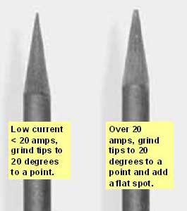
[d] Program the robot so the tungsten is a minimum of "0.060" at
the weld start, and "0.070" at the weld end.
[e] At this time
you are changing the tungsten every 50 parts. If you contaminate a new tungsten
on the first part you will have a high probability of extensive weld rework. Cut
a window in the robot door cell door, program the robot home position so the TIG
gun nozzle and tungsten is always visible to the robot operator.
[f] PROVIDE A TUNGSTEN STICKOUT GAGE: Provide the robot operator with a
tungsten gage. At any time the operator can stop the robot when it's at the home
position, and without entering the robot cell, reach through the access window
and replace and reset the tungsten. The tungsten stick out from the nozzle should
be 6 mm.