|
|
Welcome to the world's largest web site on MIG , Flux Cored and TIG. Weld Process Controls & Best Weld Practices. To optimize weld quality - productivity and get to the root cause of MIG & Flux Cored weld issues, requires something rare in the welding industry, Weld Process Control - Best Practice Expertise. The site provides the weld information and data necessary to attain the highest possible manual and robot weld quality, always at the "lowest possible weld costs".
This web site was first established in 1997 by Ed Craig. Contact Ed. ecraig@weldreality.com
Engineers - Management, flux cored weld issues and resolutions on large applications
as found in ship yards and other large weld fabrication facilities .
2018...Each year since the 1990s and likely before, on average of 300 to 500 Tankers Break Apart and sink, this is according
to the International Association of Independent Tanker Owners, known as Intertanko.
The leading cause of ships sinking was collision, but nearly as many ship also suffered from “unknown structural failures or
technical problems"..
Canadian Frigates, MIG and Flux Cored,
serious weld Issues in the 1990's and still happening in 2018:
not aware that their ship yard was in a state of Weld Process Chaos:
During the nineteen nineties, I was invited to provide a Weld Evaluation for a North East Canadian Ship Yard. The yard was building Frigates for the Canadian Navy. It took me a few hours at the yard to figure out that at this ship yard, most of the welding procedures and weld practices utilized could only be defined only as "weld engineering chaos."
The weld engineers and management at the Canadian ship yard had allowed the use of poor weld practices and the front office personnel, engineers and supervisors did not appear to understand the concepts of weld process controls or even the fundamentals of the MIG and flux cored weld processes utilized for most of the welds on the Navy Frigates. It was also interesting for me to find out out that thanks to the weld management apathy and lack of management Process Ownership, the few weld engineers employed in the yard were not allowed to tell the welders what to do. The bottom line was the ship yard weld quality and productivity was run by the yard welders, and the majority of these welders lacked an understanding of the MIG and flux cored processes utilized.
Incorrect weld process choices and weld settings for the Canadian Navy Frigates.
When you weld a 1/4 (6mm) horizontal fillet weld with MIG or flux cored wire you produce a "single pass weld" with either a MIG Spray weld, or a flux cored wire using a a high wire feed - volt setting. Both of these weld processes would provide a typical weld deposition range of approx. 9 to 12 lb/hr. In a ship yard, welding fillets, multipass fillets or groove welds, (good groove welds use fillet wire feed settings), and with a 30% hourly arc on weld duty cycle, any welder who is well managed, would deposit on average 20 to 25 pounds of MIG or flux cored weld wire per shift.
Note. You will find that most ship yards only average 8 to 15 lbs of wire per-eight hr. shift
WHEN IT COMES TO WELD COSTS, HOW GOOD IS THE MIG & FLUX CORED WELD PRODUCTION EFFICIENCY AT YOUR PROJECT?
An acceptable average MIG and Flux Cored weld wire usage per eight shift day for weld shops welding parts > 4 mm should be 20 pounds / per-shift. A highly effiicient weld shop would be depositing approx. 24 pounds per-shift. Those shops that weld thinner parts < 4 mm, should be depositing on average between 8 - 10 pounds per shift.
To compete in a global weld market in which the Chinese are now welding bridges for the state of California, North American management should at least have the capability to understand the weld quality requirements and the weld deposition rate potential per welder.
In a large weld shop where welders weld and someone else does the assemble or fitting on parts > 4 mm, if you multiply the total welder man hours by 3, you will see how many pounds of MIG or flux cored weld wire should be deposited daily. Then call the plant's purchasing manager, ask them to let you know how much wire was purchased and used in the previous year. With this information you will quickly get a grasp of where you are reference the weld you are depositing and your real weld production potential.
Note: Most of the large MIG - flux cored weld projects that I visited in 13 countries were only achieving 40 - 60% of the welds that they should have been daily deposited. To be aware of how to attain the weld production goals and train the weld personnel on how to achieve these weld production goals, please visit my Manual MIG - Flux Cored Process Control Programs.
Note: Single pass welds are fine with horizontal fillet welds up to 5/16 (8mm). When the horizontal fillet weld size required is larger than 5/16, the weld shop would have concern for side wall fusion. The solution is to then weld the large fillet using 1/4 (6mm) stringers. Do not allow manual weaves to be used for single pass fillet welds above 5/16 as lack of fusion may occur and excess weld heat (weaker HAZ - distortion ) will be generated.
In the poorly run Canadian ship yard, the two prime weld processes that were daily utilized Flux Cored and MIG were on the majority of the welds being used INCORRECTLY WITH INCORRECT WELD PRACTICES. For example to make the 1/4, (6.4mm) carbon steel, horizontal fillet welds on the Navy Frigates, the yard welders would typically apply TWO wedls that were carried out using TWO different weld PROCESSES for the ONE WELD. A simple 1/4 fillet would comprise of two weld processes,
MIG and Gas Shielded Flux Cored.
Someone forgot to tell the Canadian Navy Frigate ship yard management, that when their welders use INCORRECT WELD PROCEDURES & PATHETIC POOR FLUX CORED and MIG WELD PRACTICES, THEY WILL END UP WITH VERY COSTLY WELD DEFECTS AND LIABILITY CONSEQUENCES.
The majority of the two fillet pass welds on the Canadian Frigates would reveal extensive lack of weld fusion and weld porosity. Also the cold flux cored welds would result also in extensive lack of fusion and slag entrapment. Each day using inappropriate weld settins and practices, the 200 - 300 ship yard welders would have produced hundreds or thousands of feet of single - multiipass welds on each Navy frigate. It should come as no surprise to those reading this, that as I walked around the yard and talked to the key weld decision makers and too many welders I did not manage to talk to anyone who knew what MIG Short Circuit, Globular or Spray Transfer was, and even fewer understood the optimum working parameter range and best weld practices required for the E71T-1 flux cored wires..
Note: Many of the Canadian Frigate welds under discussion only required visual surface examination, and this is the crutch that enables the typical poor weld management and supervision to pick up a pay check.
WELD COSTS: THE AVERAGE WELD DEPOSITION RATE AT THE CANADIAN YARD WAS 4 - 7 LB/HR. The MIG short circuit - globular parameters that were used with the 0.045 (1.2mm) wires were set at a the SC typical wire feed rate of 210 to 280 ipm, (average 5 - 7 lb/hr) which typically produced 180 to 230 amps with 19 to 22 volts, (20 plus volts promotes glob and excess spatter).. Without question, the majority of these welds would result in extensive lack of weld fusion, on any carbon steel parts > 4 mm. The flux cored data that also use these settings was better suited to a poor quality "vertical up weld," The average flux cored weld deposition would have been 4 - 6 lb/hr.
IN MY PROCESS CONTROL TRAINING PROGRAMS, FLUX CORED OR MIG WELDING COSTS ARE SIMPLE:
For those few managers, engineers or supervisors that have an interest in weld process controls and weld cost info. To make a single pass, horizontal,1/4 fillet with the 0.045 flux cored wire, you would typically set approx. 500 inch/min, (average 9 - 10 lb/hr) with 27 - 28 volts. For the MIG process a wire feed rate of approx. 420 - 450 inch/min, (average 11 - 12 lb/hr).
For decades the Canadian and also the USA Navy's worst enemy
may be the poor welds produced on the ships they build.
.
I
F MANAGEMENT, ENGINEERS & WELD SUPERVISORS DO NOT FULLY UNDERSTAND WELD PROCESS CONTROLS THEY WONT UNDERSTAND "WELD COSTS" WELD DEPOSITION RATE POTENTIAL OR THE REQUIREMENTS FOR CONSISTENT OPTIMUM WELD QUALITY. THESE , ARE SUBJECTS NOT LIKELY TO BE PART OF THE DAY TO DAY WELD SHOP CONVERSATIONS:
To put salt in the Canadian Frigates ship yard management wounds, every weld produced with the low wire feed (low deposition rate) settings, took each of the 250 - 300 welders approx. 30 to 400% longer than it should have.
This Canadian yard simply had no effective weld management and ironically spent over a million dollars annually on "welder training" which resulted in extraordinary poor weld productivity and quality. Not that anyone gives a dam, but the low weld deposition rates and unnecessary weld rework could readilyy result in Canadian tax payers paying > 10 plus MILLION dollars per year on unnecessary weld labor costs.
I delivered my weld report to the yard management. The report provided the required data and practices for the yard to get it's welds to the quality and productivity that they should have been attaining.
I was later informed that my weld report never got as far as the first manager who reviewed it. The report then disappeared into the nearest garbage container. I was later told by the key weld suppler to the yard that the manager was too embarrassed to present the report to his executive team, and also he did not want the Canadian Navy Brass to be aware of the weld quality produced and the unnecessary yard over costs generated by the welds.
ALL WELD DECISION MAKERS SHOULD FOCUS ON THEIR OWN BEST WELD PRACTICES - PROCESS CONROL EXPERTISE. USING MY SELF TEACHING - PROCESS CONTROL TRAINING RESOURCES, IT'S EASY TO GENERATE MULTI-MILLION DOLLAR COST SAVINGS WITH ANY LARGE SCALE WELD PROJECTS:
Each year from 1995 to 2001, an average of 408 tankers break apart at sea or barely escape that fate, this data is according to the International Association of Independent Tanker Owners. The leading cause was collision, but nearly as many suffered Structural & Technical Failures. often a euphemism in industry circles for excessive corrosion or structural (weld) problems.
Author: A portion of the arcticle by Murray Brewster
Senior Defence writer for CBC News. Notes attached from Ed Craig.
Canadian Shipbuilding program hits snag as additional
inspection finds defective welds in the ship's Hulls.
2108: The first civilian ship built under the federal government's marquee shipbuilding program will have portions of its hull re-welded because an inspection has uncovered a series of defective weld joints, CBC News has learned. Up to 44 metres of welds on the Canadian Coast Guard Ship Sir John Franklin — which was launched only last December and has not yet entered service — will be repaired before it is handed over to the federal government early next year.
Note from Ed. Only a small portion of ships get NDT that truly evaluates the internal weld quality. If any of the ships built in Canadian or US ship yards had to undergo 100% NDT such as X-Rays, the yards would likely go out of buisness and it would due to apathetic weld management.
The Franklin is one of three offshore fisheries science vessels being constructed by Seaspan in Vancouver Canada. All three vessels were found to have the same weld defects — meaning all three will have to be re-welded in spots before entering service. The company is still investigating how the faults happened, with the help of outside experts. But officials downplayed the significance, saying welding problems occur on all projects and the extent of the overhaul represents just under five per cent of the joints on the Sir John Franklin. "While defects are unwelcome, they are far from uncommon in shipbuilding," said Tim Page, vice-president of government relations at Seaspan.
Note from Ed..Remember usually around 90% of the welds are only subject to visual examintion and those officials and Tim Page are full of BS.
Cracks:
The three science ships, intended to monitor the health of fish stocks, represent the first wave of 17 civilian-grade vessels — worth $7 billion — to be constructed on the West Coast. Irving Shipbuilding, in Halifax, is the other yard, where combat vessels are being constructed.
The microscopic welding cracks initially were discovered three months ago on one of the science vessels, which is still under construction in North Vancouver. A coast guard team monitoring construction flagged the issue as part of a detailed review, the company acknowledged. The defects were spotted after the first two ships, including the Franklin, had passed their initial inspections. Subsequent retesting on all three vessels turned up the same faults. Whether the problem was due to human error or equipment failure is not clear, but the company said it has switched to another welding method for the time being.
Note from Ed. The lack of weld process ignorance is amazing
The Franklin — named for the famed Royal Navy Arctic explorer Sir John Franklin — has been pulled from the water in Victoria, B.C., where it was towed for outfitting and sea trials. The 63 metre vessel was launched with much fanfare last December in Vancouver. At the time, the former chief executive officer of Seaspan expressed pride in the accomplishment.
The federal Department of Finance prepared a 25-page briefing on the plan and its fiscal implications; a heavily redacted version was released under Access to Information legislation.
The cracked welds on the fisheries science vessels should serve as an object lesson for those overseeing the programs, said a procurement expert. "I think it should definitely strengthen the call to have the government refresh it and take a hard look at its approach for managing these contracts," said Dave Perry of the Canadian Global Affairs Institute.
"On a project like this, you should be expecting some degree of problems. It's just a question of how significant they are and whether or not they're the types of things that generally tend to happen on projects like this — or if they're kind of out of the ordinary."
Note from Ed. Above again is BS. The steels and processes utilized have been around for decades, the real issue is the lack of management and engineering weld process control expertise.The issue did catch the attention of the Canadian Navy, which is waiting for Seaspan to build its supply ships.The National Defence has asked the company to examine its welding procedures for the joint support ships to ensure there won't be a repeat.
2018 note from Ed. Unless both the Canadian Navy and Canadian ship yard management and engineers wake up to their own lack of weld process controls and best weld practice expertise, the weld and too common corrosion defects will continue as it's done since the 1940s.
.
Weld Management - Expertise - Responsibility - Accountability - Ownership.
Wow what a surprise, it looks like there are some managers, engineers
and supervisors in this major USA ship yard's front office, that need a lesson in
establishing weld process controls and best weld practices.
MILLIONS AND MILLIONS OF TAX PAYERS DOLLARS IN UNNECESSARY WELD REPAIRS.
A lack of Weld Management - Engineering WELD Accountability - Responsibility & Ownership, or in reality simply another day in a West Coast SHIP YARD.
Northrup Grumman Ship Systems in Pascagoula, Miss, built the San Antonio ship at a cost of $1.2 billion, which was only approx. $400 million over budget. This ship failed to complete a series of sea trials in late March, and then faced another $36 plus million dollars in repairs during the next three months. The San Antonio has been plagued by mechanical and structural problems since the Navy took ownership two years late, in July 2005.
While the Northrup management and Navy allowed 400 million dollars over budget for one of it's Navy ships, the Korean ship yard management could have built 3 of the world's largest ships.
2015. OSCAR: In 2015 this was the world's largest ship. Oscar holds almost 20.000 containers, it's 1297 feet long, 240 feet high and 194 feet wide. This steel fabrication wonder was built for the very low sum of 140 million dollars. Compare the 140 million dollar ship building costs with the typical weld and mecahanical rework costs of a typical Navy ship yard vessel.2017: When you see what's happening to fabrication - weld - engineering costs here in North America , please remember that it was only a few years ago that the USA had the world's most capable and cost effective ship yards.
Today in North America when we look at our general lack of industry - Navy management / engineering process ownership, we need to go way beyond labor costs as the root cause of our mfg, / job demise. Perhaps we also should spend a little more effort to examine our engineering and fabrication capability. You would think that engineering - fabrication capability would be important to a country which has an economy that for decades has been held together by tax payer Defence Projects.
At least here you can become even smarter than the Koreans, that is
if you learn these Weld Process Control and Best Weld Practice Programs..
Most American tax payers are rarely aware of where their taxes go, and with goverment projects, weld rework costs can too often be extraordinary.
According to the program office the LPD 17 Amphibious Transport Dock, which was delivered to the Navy in July 2005, experienced numerous quality problems of varying degrees that significantly impacted the ship’s mission. These problems contributed to a delay of 3 years in the delivery of the ship and a cost increase of $846 million.
In June 2007, the Secretary of the Navy sent a letter to the Chairman of the Board of Northrop Grumman expressing his concerns for the contractor’s ability to construct and deliver ships that conform to the quality standards maintained by the Navy and that adhere to the cost and schedule commitments agreed upon. Northrop Grumman’s Chairman acknowledged that the company was aware of the problems and was working on improving its processes.
The LPD 17 encountered a problem with the isolators on titanium piping. The isolators are used to separate different types of metals to keep them from corroding. The problem was discovered in 2006, about a year after the launch of the first ship. According to DOD program officials, the titanium piping is used throughout the ship because it is lighter than the traditional copper-nickel piping and has a longer service life. However, it has not been used much in naval surface ships or by the American shipbuilding industry, and therefore required new manufacturing and installation processes. According to the program office, these processes were being developed as Northrop Grumman Ship Systems was building the ship. In addition, designs for the piping hangers, which hold the piping in place, as well as tests of the isolators were subsequently delayed. When the titanium piping on the ship was changed, the hanger design had to be modified as well. The final hanger design was not completed until about 90 percent of the titanium piping was already on the ship, which resulted in additional rework and schedule delays.
Note from Ed. In 2007, welding Titanium was in 2007 a simple task if both the Navy and Northrup management and engineers knew what they were doing, and they had selected tth TIP TIG process instead of the regular GTAW process. TIP TIG at that time had been available for approx. 6 - 7 years. See TIP TIG at this site to find out why this Titanium project would not have been a challenge.
Note from Ed: Again TIP TIG would have simplified any pipe welds. Also if the workers lacked any knowlege and are not doing their job, the management has that responsibility to make sure they have the training to be qualified
INVESTIGATION OF FRACTURED STEEL PLATES REMOVED FROM WELDING SHIPS.
Corporate Author : PENNSYLVANIA STATE UNIV UNIVERSITY PARK
Personal Author(s) : Williams, M. L. ; Meyerson, M. R. ; Kluge, G. L. ; Dale, L. R.
Abstract : Samples of fractured plates from 72 ships were examined, and various laboratory examinations and tests were made on 113 plates selected from these samples. Information regarding the structural failures involved was obtained from the cooperating agencies, and the failures were analysed on the basis of this information combined with the results of the laboratory investigations. The ship weld failures usually occurred at low temperatures, and the origin of the fractures could be traced, invariably, to a point of stress concentration at a geometrical or metallurgical notch resulting from design details or from weld defects.
Note from me: Over fifty years have passed since the above reports. The question is in 2017, when will ship yards get control of the common welding processes they utilize?
THE SUPER STRUCTURE ON FFG 7 CLASS SHIPS HAS EXPERIENCED EXTENSIVE CRACKING. THE CAUSE OF THE CRACKING HAS BEEN DETERMINED TO BE A COMBINATION OF HIGH DESIGN STRESS COUPLED WITH UNEXCUSABLE POOR WELD QUALITY.
IN THIS USA SHIP YARD, I PROVIDED FOR THE YARD, FLUX CORED WELD PROCESS CONTROL - BEST WELD PRACTICE TRAINING. MY TRAINING PROGRAM REDUCED THE OIL TANKER CONSTRUCTION WELD REPAIR COSTS BY MORE THAN 6 MILLION DOLLARS PER SHIP.
In building a fleet of oil tankers in Philadelphia, Aker Kvaerner, a global ship building company had budgeted a few hundred thousand dollars per-ship for it's projected ship weld repairs. In 2007, I was called in to help this yard with it's weld quality and productivity problems. At this time the weld repair costs per oil tanker was approx. EIGHT million dollars.
The prime manual weld process at this USA ship yard, was the Gas Shielded Flux Cored weld process. Most of the 300 welders in the yard used E71T-1 (1.2 mm) flux cored wires to weld all position, Vee Groove, 9 to 25mm, steel joints that used ceramic backing for the open roots.
Like many ship yards, the Aker management, engineers and QA personnel knew little about the flux cored and MIG processes, their experience was usually with the SMAW (stick) process, a process in which weld skills is the prime requirement and minimal weld process expertise is requied.In this yard, as it is with too many large scale weld projects, the flux cored welder training focus was on the "welder's skills", and the skills taught had more to do with the SMAW process and were not the optimum skills - practices required for flux cored. As is common in most ship yards, the training provided no best weld practices and process controls, both of which are essential to optimize both flux cored and MIG weld quality and productivity.
To work at the yard, the welders had to pass an all position, flux cored weld tests with ceramic backed vee groove welds, (6 mm root gaps) The welds were to be made in accordance with the yards weld procedures.
TOO OFTEN THOSE CAREFULLY CONTROLLED , "WELD QUALIFICATION TESTS" ARE IRRELEVANT TO THE WELDS MADE ON THE ACTUAL WELD WELD APPLICATIONS.
It's important to emphasize, that like many code quality weld applications, the weld - welder qualification tests will too often have little in common with the real world weld joints typically found in the weld shop or the yard.
This ship yard was managed by managers - engineers and supervisors who while comfortable around a box of stick electrodes, lacked the awareness - expertise of the unique requirements necessary to attain consistent optimum manual or automated flux cored weld quality for those ceramic backed steel groove welds. In the last five decades, the lack of valuable weld process control - best practice expertise appears to be common on large scale weld projects, and it does not take a rocket scientist to figure out the future weld liability and the weld cost consequences.
THE EXTRAORDINARY OVER BUDGET USA SHIP YARD WELD REWORK COSTS COULD NOT CHANGE TILL I INSISTED THAT ALL THOSE INVOLVED, INCLUDING THE LACK OF OWNERSHIP, FRONT OFFICE PERSONNEL ATTEND MY TRAINING SO THEY WOULD ALL FULLY UNDERSTAND THE WELD PROCESSES THEY OWNED AND WALK THE SAME PATH TO MEET THEIR WELD QUALITY - PRODUCTIVITY GOALS.
For the Flux Cored Weld Best Practices - Process Control Training Program that I was to present, I insisted that all the welders, supervisors, engineers, managers and QA personnel in the yard participate in my unique
Note for Bean Counters: This weld process training program requires approx. ten hours, "five hours classroom and five hours hands on".
With my friend Tom O'Malley assisting, Tom in light blue jkt on right died in Feb. 2015.. RIP TOM. In a few weeks, we completd the training for 300 welders and the yards newly eductated weld decision makers. After the training was complete, the ship yard QA department was given the responsibility to evaluate the weld cost saving results through the weekly reductions with the ship's weld rework. Three months after the training, the ship yard QA department indicated a 50 - 60% reduction in the required weld rework per-ship. The ship yard management reported that the reduced weld rework, labour and NDT costs, would result "at that time" in a weld cost savings of approx. 4 million dollars per-ship. As the weld rework was still decreasing further cost reductions were projected and dont forget I have not discussed the increased weld productivity that was attained from the welders using the correct (higher) wire feed settings.
HOW MANY MORE DECADES WILL IT TAKE FOR SHIP YARD MANAGERS TO REALIZE THAT THE SMAW PROCESS HAS NOTHING IN COMMON WITH MIG OR FLUX CORED?
FOCUS ON SKILLS AND NO FOCUS ON PROCESS EXPERTISE: It's not unusual for weld personnel to have many weeks of flux cored hands on training at global ship yards, and then at the training completion find that when it comes to MIG and flux cored welds, the weld personnel that have under gone weld training will do the following;
[a] A PLAY AROUND with two simple MIG or flux cored weld controls that have not changed in sixty years, The welders and their supervisors will rarely be able to dial in the optimum flux cored weld settings for the Vee groove root, hot pass, fill pass and cap passes. And don't ask that welder to tell you the optimum MIG settings for that common horizontal 1/4 fillet weld.
[b] NOT BE AWARE OF PROCESS CONTROLS AND LIMITS OF THEIR WELD ADJUSTMENTS: Instead of optimizing the welds through the MIG weld equipment controls, many welders will typically find one weld setting and if they cant find one, the welder may copy the settings of another welder although that welder is doing a very different weld. A welder should be able to make optimum weld parameter changes that suit the conditions they have to deal with. Imagine how annoyed a machine shop supervisor would be, if his lath and milling machine operators used one control setting for every different job they were given.
[c] NOT BE AWARE OF THE BEST WELD PRACTICES? As they have rarely received best practice training, it should be no surprise that most MIG and flux cored welders will not utilize the optimum weld practices - techniques required for either the MIG or flux cored process.
[d] NOT BE AWARE OF THEIR INFLUENCE ON WELD COSTS? Lack of management, engineer, supervisor and welder awareness of the wire feed to weld deposition relationship and the weld deposition rate potential for the common flux cored or MIG welds certainly makes it difficult to be competitive and to control weld costs.
A BREAK DOWN OF THE WELD COST SAVINGS GENERATED FOR THIS USA SHIP YARD:
Examine the following ship yard weld cost reduction and the weld benefits attained from my unique process control training program. Many mangers may not be keen on training as in the past the weld training did not improve the weld quality or productivity. (Managers, if you dont provide the right training you don't get the results). Training cost money, and the larger the weld shop the greater the training costs. With this in mind it should be no surprise to find some one in management that may be worried about the production man hours lost for training their employees.
Cost Benefits from Weld Best Practices & Weld Process Control Training:
The Acker Weld Flux Cored Taining that I produced and provided, (available here) required 300 x 8 man/hrs. = 2400 man hours at an approx. weld labor overhead cost of $30/hr. The base labour training cost for the ship yard training was $72,000. To this add the actual training and material costs was approx. $100,000. Total training costs for the 300 welders was approx. $172,000.
Ship Yard Weld Rework Cost Reduction Savings Per-Ship:
The initial weld improvement results revealed an instant savings of four million dollars. With management - engineering and supervision focus on maintaining the skills - process control expertise required, the reduction in weld rework costs will continue and could easily reach 7 million dollars on each oil tanker produced.
Ship Yard Weld Cost Reduction from Increased Weld Productivity:An unreported weld cost fact from the Aker yard was the changes that I created in the development of the new weld procedures. My weld procedures generated a dramatic increase in the gas shielded flux cored wire feed rates, (increasing the weld deposition rates). The new weld procedures increased the daily weld productivity potential per-man in the range from 25 to 35%. If the managers and supervisors kept their focus on weld deposition potential, it would be easy for the yard to attain a weld labor cost reduction per ship of between four and five million dollars.
Ship Yard Weld Cost Reductions from welding the Correct Size Weld Joints:
If this ship yard manufacturing management, engineers, supervisors and fitters, decided to provide the weld joints in accoradance with the design dimensions and tolerances it would be easy to reduce the weld labor and rework by another 1 to 2 million dollars per-ship.
Ship Yard Management - Ownership - Responsibility - Accountability.
The weld quality - labor cost reduction savings for each oil tanker could if well managed readily achieve "8 to 13 million dollars" per-ship. Larger ships built at this yard would provide increased weld cost savings. The welders have the skills which when combined with the best practices and process control training they recieved has given them the resources they require. To sustain the weld cost savings and weld quality, a commitement is required from the yard management to ensure that they and their engineers and supervisors maintain ownership of the weld processes utilized and be responsible and accountable for the weld quality and productivity attained.
Note I took > 2500 - 3000 hours to develop both the Flux Cored - MIG training programs available at this site. My unique Weld Control Clock Method simplifies the training or self teaching, this is a method I developed over three decades. This program can be used for any gas shielded flux cored alloys or applications, in my training programs.
My thanks to the Aker Kvaerner management for allowing me to be their short term catalyst for welding change.
1945 or 2015, when will they ever learn?
In the good old STICK (SMAW) weld days which for some projects is on-going, some steel ships broke apart at the welds before they left the dry dock, these ships and the other catastrophic structural ship failures that occurred at sea, were often a result of Low Hydrogen Cracking, poor weld procedures and practices, steels with poor chemistry (high impurities) and design ignorance of plate / weld mechanical properties and the influence of cold temperatures.
Since the 1980's the majority of ships have been built from high quality,low carbon steels and welded with low hydrogen SMAW - MIG and flux cored consumables. You would have thought these two important attributes would have resolved the catastrophic ship failure issues that occur in >2008.
Lets face it, welds on low carbon steels, are typically supposed to surpass the strength and ductility of the base steels and if the welds are applied correctly, the welds and surrounding base metals are not supposed to fail.
The reality is however different, while many ships and oil platforms have plate and pipe that will be affected by rust, during unforeseen circumstances or severe weather while the steel parts impregnated with rust stay intact, the welds and weld heat affected zones will tear apart like a wet paper bag.
03/ 2007: Is it possible that the global ship building flux cored, lack of best weld practices and lack of weld process controls are partially responsible for many of the catastrophic failures that sink many ships each year?
A COMMON SHIP YARD FABRICATION ATTITUDE.
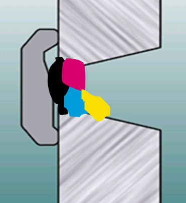
THE USA SHIP YARD HAD EUROPEAN, HIGHLY QUALIFIED SHIP BUILDING MANAGEMENT, AND A LARGE QA AND ENGINEERING DEPARTMENT, YET THEY ALLOWED WELD JOINTS LIKE THIS..
It's a weld reality that the QA departments in many ship yards and oil platform yards, while looking for weld defects the QA department personnel will place minimal focus on the design fit tolerances and the quality standards that are supposed to be applied to the part fit and weld edge preparations. Its also a fact that pre-heat and interpass weld temperatures are often not utilized when they could provide good weld / part benefits.
The picture on the left is a flux cored weld edge prep (made in 2007) at a major USA ship yard. Yes the gap opening is larger than one inch and that is ice and water surrounding the weld joint. On this joint there was no weld preheat applied and no interpass weld temperatures applied during the numerous welds. To add to this pathetic weld situation, the mill scale was left on the groove edges and cutting oxides were left on the groove surfaces. Weld joints like this shoud never be allowed especially in these industries.
The increased root openings not only dramatically adds to the weld labor costs and increased potential for weld defects, the weld heat from the additional weld passes has a tremendous negative influence on the weld's HAZ (heat affected zones).
DOES A STEEL BACKED, 6 mm ROOT GAP ON SHIPS PLATE, PROVIDE THE SAME HAZ MECHANICAL PROPERTIES, WHEN THAT ROOT GAP IS ALLOWED TO INCREASE IN THE RANGE OF 8 TO 25 mm?
WITH THE EXTRA WELD PASSES FROM THE OVER SIZED ROOT WELDS, THE RESULTING , INCREASED WELD HEAT AND INCREASED WELD DEFECTS WILL HAVE DRAMATIC NEGATIVE RESULTS FOR BOTH THE WELD AND WELD JOINT INTEGRITY. WITH THIS IN MIND, YOU WOULD EXPECT THE SHIP YARD ENGINEERS TO PROVIDE STRICTER SHIP YARD WELD REQUIREMENTS AND ENSURE THE CORRECT FABRICATION AND WELD CONTROLS ARE APPLIED.
Weld - steel qualification tests for critcal ship weld plate joints are typically taken from optimum weld joints with specified max root gap openings. It would be of interest, if the navy and ship building industry, both of which turn a blind eye or enable welds that allow extensive, plus, open root tolerances, would provide the necessay research to find out the following;
[a] what the negative weld heat influence will be from the numerous extra weld passes.
[b] what the negative consequences will be from the combinations of the extra weld defect buildup and extra weld heat would be on the mechanical properties,
[c] what is the real world maximum root gap cut off point before the mechanical properties will be outside those specified by the ship's designers? After this research, I would anticipate a dramatic reduction in the open root tolerances, more focus on interpass temperature controls and and stricter part fit controls in the fab shops.
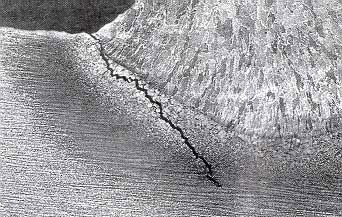
The additional HAZ weld heat provides many questions about the mechanical properties being achieved with many weld joints. Every time I see photos of ships that unexpectantly tear apart at sea, and you see that nice clean straight tear where the welds HAZ is located I think about these weld situations.
Quick, before it sinks, examine how nice and clean those catastrophic failure tears are, right down the welding seams and the weld HAZ..
2007: The weld failures on this ship occurred in the locations in which the welds should have been sound, as they would have be subject to NDT. With ship welds we need more focus on the weld quality that is being accepted and on the mechanical properties being attained in the weld's HAZ.
2007: It's a weld reality that in ship yards and on other mega oil and natural gas projects, that many unacceptable variables will happen to the weld joints and welds and those "variables that impact the welds are typically not considered in the pre-qualification welder procedures generated".
When the weld personnel are not supplied with the process control training necessary to deal with the weld shop variables, the welders will typically play with the weld controls and not provide optimum weld settings to deal with the weld situations.
Weld Quality Standards will have a different meaning for each company that builds ships or oil platforms. One thing most QA departments will have in common, is their weld quality focus will be on "finding rather than preventing weld defects".
Have we learnt anything about welding ships in the last six decades?
29/07 Note from Ed:
Designers and metallurgists will typically look to the ship's design, steel - alloy compositions, environment, water temp, weather and the formation of rust for the causes of many catastrophic ship failures. I wonder how many designers will take into account that on any global built ship the NDT that examines the internal weld quality is only applied to a small percentage of the ships welds.
IRRESPECTIVE OF THE WELD CODES, COMMON SENSE WOULD ENSURE THAT ENGINEERS CREATE PRE- QUALIFICATION WELD TESTS THAT ALLOW FOR THE REAL WORLD "WORSE CASE WELD SITUATIONS THAT ARE LIKELY TO TAKE PLACE WITH THE INTENDED WELD APPLICATIONS".
Poor Welds and the Dramatic Consequences.
Often a ships will break apart in the weld or along the weld
seam HAZ, and it does not take much of a storm to cause the damage.
While the ABS code, Navy or any ship builder will stipulate a maximum root gap allowance in most instances its rarely adhered to. The weld reality is weld and material metallurgical weld qualification tests should always be carried out with the maximum allowable root gaps and those root gap dimensions must have strict min and max tolerances that must be followed. Unfortunately as the photo on the left indicates this is the real world weld joints that are rarely shown in the engineers office.
When building merchant or naval vessesls, the too common poor control of the weld joint will often leave edge preps that have irregular, oxide and scale laden surfaces. The edge preps may also not have the required pre-heat on those cold or wet days. The wet plates or cold plates, lack of pre-heat combined, oxides - scale and frequent lack of interpass controls with innapropriate weld parameters, techniques and practices, and the usual lack of care of the consumables leads to extensive lack of weld fusion, weld slag inclusions, porosity and lower than required plate / weld mechanical properties..
As only a small portion of a ship's welds are typically subject to NDT, both the navy and merchant navy would do well to put a renewed focus on weld process control training that is directed at weld defect prevention and good weld practices. All managers need to be aware that it's just as easy to produce optimum quality welds as it is to produce poor welds.
Was the ship's or OIL Platform demise from a
freak of nature, or from the usual poor quality welds?
The following are a sample of recent News Paper or Web Reports on typical weld and related issues that have occured in ship yards. It's true that with large scale weld fabrications it should be no surprise that they are extensive weld issues. It just seems strange that few managers today seem to want to take opportunity to take ownership ot their processes and control of the many variables that can provide dramatic weld cost reductions for their organizations.
POOR SHIP YARD AND NAVY WELD MANAGEMENT LEADS TO THIS. When building the USS Nimitz, as reported by the Navy, only ONE WELD out of approx. 100 tested, passed the NDT.
MOST DESIGNERS ASSUME THAT THE SHIPS OR OIL PLATFORMS THAT THEY DESIGN, WILL BE BUILT IN ACCORDANCE WITH THE WELD SPECIFICATIONS PROVIDED. THE WELD REALITY IS FEW ARE. THE REASON WHY MANAGEMENT - ENGINEERS GET AWAY WITH POOR WELD CONTROLS AND PRACTICES IS, IT'S DIFFICULT TO TEST AND CONFIRM THE OVERALL WELD INTEGRITY ONCE THE SHIP YARD OR OIL PLATFORM IS ON THE OCEAN FLOOR.
LACK OF WELD EVOLUTION: The amount or type of weld defects typically found in a ship's construction in 2015, has hardly changed from the defects found six decades ago.
1948 - 2018 SO WHATS NEW? In the 1940's, poor quality stick (SMAW) welds were the norm. The weld quality was further influenced by electrode issues combined with poor quality steels and poor weld practices. The end result was numerous Liberty ships suffered from catastrophic weld & steel failures.
Seventy years later, in general (there are of course exceptions) in the weld industry we have achieved what.? Today we have a superior flux cored wires for those all position ship plate - pipe welds. We also have the MIG process and good automated weld equipment. We also weld on far superior quality steels, yet due to the global lack of weld process control expertise, the too common poor weld practices and the ineffective (we take no ownership) weld management, ships and oil platforms are riddled with costly weld defects and these applications are still at risk for catastrophic failures.
<1960: 5000 liberty ships built, 1000 catastrophic
failures right down te weld seam.
Decades later,oil platforms heading down to the ocean floor
For those looking for the structural security attained from the double hull construction that will occur when building large ships or more costly ships, keep in mind that unless ship yards change their approach to weld best practices and process controls, the double hull ships may simply enable double the amount of bad welds.
HOW RELEVANT IS STATE OF THE ART SHIP DESIGN WITHOUT SOUND WELDS:
2006: Each week one or two global ships sink, many as a result of weakened
structures from corrosion.
300 - 400 ships sink annualy and many as a result of bad weld practices.
SHIP YARDS AND CAR PLANTS HAVE SOMETHING IN COMMON. The US automotive industry that this year had 60 million vehicle recalls, and billions of dollars lost annualy to recalls due to poor engineering and lack of effective mfg practices. The auto industry management loves the infamous and highly ineffective Six Sigma (SS) Crutch. This apathetic management crutch is now heading to other industries whos management also requires a crutch to compensate for their lack of expertise. Ship yards and other large weld fab shops are showing interest in the SS even after it has failed with the majority of manual and robot MIG and flux cored weld applications found in US automotive and truck plants.
Remember when it comes to welding, MANAGEMENT does not need a salesman or a crutch, however most managers will benefit from reading about their necessary weld best practices and process control requirements.
THE TYPICAL FAILURE OF QA SYTEMS in weld facilities is that the program typically promotes finding, rather than preventing weld defects.
THE COMMON QA WELD INSPECTION PRACTICES USED THROUGHOUT THE GLOBAL WELD INDUSTRY OFTEN DOES LITTLE TO REDUCE WELD REJECTS, REWORK OR WELD LIABILITY POTENTIAL..
While that QA manager focuses on the ISO and his never ending after the weld fact inspection reports, the lack of affective process control training, the lack of weld best practices and the lack of management - supervision process expertise and process ownership in his organization leaves many of the welds in a questionable situation.
Be a Professional with the weld
processes & consumables you daily utilize.
A note from E Craig. 03/2007:
WELDING SKILLS ARE JUST ONE SMALL PART OF BEING A WELD PROFFESIONAL....A ship yard may use half to a million pounds of flux cored weld wire each year, however it's rare to find a ship yard that has management and engineers who understand or have established Best Weld Practices and implemented effective Flux Cored Weld Process Control Training for the weld personnel. (This is not the SKILL training typically provided).
How many ship yard managers and supervisors are aware of the following?
For decades the global shipyard focus has been on the welder's "stick welding skills while the majority of global ship yard welders that weld with the flux cored - MIG process, lack weld best practices - process control and consumable expertise.
Too many weld personnel in ship yards will daily use the unsuitable techniques and skills they learnt with the lower weld energy, lower weld deposition stick welding process.
With the flux cored process, the variable size root gaps and the placement of weld across none conductive ceramic backing requires unique weld considerations and specific instructions for the all position, root, fill and cap weld passes. A visit to any global ship yard, would reveal that few welders, supervisors or "engineers" are aware of the flux cored process and ceramic requirements necessary for consistent weld optimisation.
2008: It's a sad comment in a time when MIG and flux cored weld defects inundate ships and oil platform construction, that at many global ship yards, weld apprentices will spend more time practicing with stick electrodes than they will with MIG and flux cored consumables. It's also a weld reality that many weld instructors when providing MIG and flux cored training, will teach the apprentices inappropriate stick welding practices and techniques. You dont want to ask any weld instructor in a ship yard this fundamental MIG question. " What is the wire feed and current start point of spray transfer with the world's most common 0.045, E70S-6 MIG wire and argon - 20% CO2"..
FACT: YOU SIMPLY CANNOT CONTROL THE WELD QUALITY - PRODUCTIVITY
AND COSTS, IF YOU CANNOT FULLY CONTROL THE PROCESS.
Try the following fundamental weld process questions.
[] Fundamental MIG Process Control Weld Test
[] Fundamental Flux Cored Process Control Weld Test.[] Ed's Unique, MIG and Flux Cored Weld Process Control Training Resources
Someone needs a lesson in ship building.
Accountability - Responsibility - Ownership. 36 million in repairs and 400 million
over budget & the seniior management and engineers are still on the job.
THANK GOD IT'S ONLY THE TAX PAYERS DOLLARS:
NORFOLK - The new amphibious ship San Antonio failed to complete a series of sea trials in late March, and faces $36 million in repairs during the next three months. The San Antonio has been plagued by mechanical and structural problems since the Navy took ownership two years late, in July 2005. Northrup Grumman Ship Systems in Pascagoula, Miss, built the ship at a cost of $1.2 billion, roughly $400 million over budget.With optimum flux cored weld consumables and extensive use of a grinder for the slag and worm tracks that are part of the process, the gas shielded flux cored process is perfectly able to produce acceptable, all position quality welds on any steel applications, as long as those applications have optimum weld procedures, trained weld personnel and weld joints that meet the design and code criteria. The bottom line is MIG or flux cored welds on any ship should be the strongest part of the ship. The reality with too many structures welds are creating the weakest link.
WHEN I WAS THE WELD MANAGER AT THE AKER KAVERNER PHILY NAVAL SHIP YARD. APART FROM EDUCATING THE ENGINEERS AND MANAGERS IN THE FRONT OFFICE I ALSO WANTED TO FIX WAS THE LACK OF WELD PROCESS CONTROL EXPERTISE IN THE SHIP YARD'S QA DEPARTMENT.
For decades, on many mega weld projects, a typical QA / CWI primary function has been to "find fault after the weld completion". With minimal cost managers could provide my MIG and Flux Cored Weld Process Control - Best Weld Practice Training Programs and demand that their weld inspection personnel learn the requirements necessay to prevent the MIG or flux cored weld defects. The reduction in weld defects, less weld rework and much lower NDT costs, has to have a big impact on the companies bottom line.
If the guys in the front office don't fully understand weld costs, who is going to understand the requirements necessary to attain optimum quality welds at the lowest possible cost?.
There were three individuals, the weld manager, engineer and supervisor having a weld meeting in the ship yard managers office. The meeting was called to discuss the reasons for the increasing weld costs associated with the weld rework. Most of the yard's welds produced were made on fabricated components that require simple 6 mm, 1/4 flux cored fillet welds and similar size groove welds. The discussion on weld costs was frustrating as not one person seemed to have an understanding about the subject. The typical weld procedure was passed around with information on the weld consumable type and size, the wire feed rates and the volts being utilized.
At this like many weld meetings, there was much heated discussion and finger pointing at the those afternoon shift guys. The manager who was a pragmatic individual (admits he knows little about weld processes and weld costs), stands and hits the table with his fist. He looks around the room and says, "gentlemen there appears to be much confusion here about MIG and Flux cored, and little evidence of any expertise. Is there one in this room that can tell me the real cost of a 1/4 fillet weld one meter in length"?.
Note from Ed. Please don't shoot the messanger.
Sometimes I feel that my comments on this site may be seen by some as a little too critical, however there is a reason this site is called "weld reality" and I don't just criticize, I provide highly effective practical weld quality - productivity and cost solutions. To those who are interested in weld best practices and process controls or weld cost simplification, click here.
Concerned about Weld Costs and Weld Liability Consequences?
For those weld shop managers and engineers that live behind glass walls and are rearing up in defensive exasperation at my hands off, inexperienced manager - supervision and engineer comments, and my criticism for the general lack of global lack of process control - best practice expertise, please remember that their will be thousands of weld shops this year that will have to deal with lower weld labor costs from other companies in other states / provinces or countries, over budget weld costs, inconsistent and poor weld production efficiency, over budget NDT costs, and extra weld rework costs.
The typical common unexpected weld - part issues will of course lead to tighter production schedules which typically makes the weld situation worse as the weld shop supervision now has to drive more production before quality. And lets not forget, the lack of process ownership ensures all involved will continue to work too many hours and loose too much sleep.
WELDAPPLICATION LIABILITY CONSEQUENCES ARE NUMEROUS ..
Every person who makes a weld decision, should learn weld process controls and understand the requirements to prevent defective welds
He now She has only been spouting this message for more than 50 years
and with all the money she makes from giving weld advice, she has been able
Finally Ed now Em made the down payment on her dream "house boat".
I wonder how many weld shop managers, supervisors, technicians and engineers would last in their jobs, if every weld they were responsible for was given a 100% UT or radiograph examination?
This Aker ship yard welder was allowed to weld USA oil tankers for three years,
and this was the welders best attempt at a welder requalification test.|
The weld equipment and consuambles purchased in a weld shop are always a reflection of the weld or fabrication managers expertise.
PURCHASE OF RIDICULOUS WELD EQUIPMENT
AND LACK OF FUNDAMENTAL BEST WELD
PRACTICES AND WELD PROCESS CONTROL EXPERTISE..
Take a moment look around your weld shop. Watch as the weld personnel "play with their MIG and flux cored weld controls". Evaluate why you are using a wide variety of unnecessary weld consumables and weld equipment. Go to your gas cylinder rack and ask your self whay there are more than two gas mixes. Chat with the purchasing mgr and find out how much was spent last year on grinding wheels and other equipment used for cleaning welds. And last, find out how much was paid last year for service, repair and maintenance costs" associated with the electronically sensitive welding equipment and weld guns purchased.
SHOULD THERE BE DOUBLE STANDARDS APPLIED TO WELDS AND
SHOULD THE SO CALLED CRITICAL SHIP WELDS BE MANUAL OR AUTOMATIC?
In my world every weld produced on a ship or used to fabricate a work bench should be considered critical, after all, whats the purpose of a weld? and why would you not ensure every weld produced is optimum. Also why would any manager allow double standards for welds:
In the ship yard, the structural welds in the center area of the ships are considered critical and subject to internal NDT weld evaluation. When NDT finds defects in these welds, then more weld area is subject to the NDT. This has great weld cost repercussions for the ship builder so these welds are given extra consideration and often the best welders are used on these joints. The point is in any facility that welds, if the correct training is provided there should be no best welders. Welding is not rocket science and there is only one standard that can be applied to all welds. If after the proper training is provided, you get rid of the welders who cannot meet that standard.
In many of the weld facilities that I visit, I note manual welders typically will make long fillet or vee groove welds, when low cost, easy to set up, automatic weld carriage equipment is on a shelf gathering dust. Controlling weld speed, weld weaves and wire stickout is essential if you want to attain consistent, optimum, uniform weld quality.
In the encouragement for flux cored or MIG weld automation, one of the problems ship and oil platform companies have, is that due to lack of weld process expertise, especially with the supervisors who should be providing the automation weld training, many welders do not know the correct data to dial in for the common 3/16 - 1/4 - 5/16 fillet welds. Ask 10 welders in a yard what is the MIG or flux cored "wire feed and weld travel rate settings" are for a 1/4 (6 mm) fillet weld and I guarantee you will get 10 different answers.
I have assisted ship yards in the USA, and Canada and in Europe. At the yards I worked with Norwegian, Swedish, Danish, German, Polish Italian. English, Korean, Japanese, Yanks and Canadians and and don't forget those tenacious thick skinned, highly intelligent, hairy, canny Scottish weld personnel. My experiences with these hard working, great characters indicated that the majority played around with their weld controls and none had ever received MIG or flux cored weld best practice - process control training, or training in dealing with ceramic backed welds.
From my ship yard experiences, i developed thicker skin, an increased sense of humour and also developed the following flux cored, CD. Best Practices - Process Control Training Resources. This program is applicable to all position, open root, steel and ceramic backed, pipe and plate, fillets and vee groove welds.
For Ed's "MIG and Flux Cored" Weld Best Practices - Process Control Training Resources.
WELD MANAGEMENT STARTS WITH "WELD PROCESS / EQUIPMENT AWARENESS":
The first step for ship yard management is be aware of the level of weld process control expertise and reponsibility of the key weld decision makers in the yard. Lets face it, If these guys knew what was needed to minimize weld defects and optimize weld productivity, then the weld and rework costs would not be out of control.
Weld quality responsibility should be in the hands of managers, engineers, technicians and supervisors. Typically the weak link in this chain are the weld or fabrication supervisors. The irony is the supervisors are given more responsibilty for the welders than the engineers and technicians get. Notice that QA persons who find weld defects after the welds are complete are not included.
IF AN ENGINEER IN A SHIP YARD THINKS A WELDER IS NOT CAPABLE OF PRODUCING THE WELD QUALITY DESIRED, HIS OPINION ON THAT WELDER SHOULD HAVE MORE MEANING THAN THE OPINION OF A PRODUCTION OR WELD SUPERVISOR.
The second step for ship yard management is the managers have to be aware that the weld equipment, process and consumables used in their yard rarely reach their full weld quality and productivity potential. The soution to this is in the training programs provided. Yard management have to be aware that the MIG and flux cored welder training programs provided for weld personnel are obviously not effective, therefore training changes are required and training focus is necessary on teaching all weld personnel best weld practices and weld process controls
The ship yard management needs to be aware that the stick (SMAW) weldesr with 20 years experience typically only brings incorrect techniques and bad weld practices to the MIG and flux cored process? There is a global shortage of welders. If the weld management was aware that when new welders walk into their yard, few will have seen a ceramic backed root gap. If something like ceramic backing is unique or rarely utilized in other industries, that means welder's need to undersatnd the best practices and process controls necessary for welding on none conductive ceramics.
As in 2017 its sometimes difficult to hire drug free welders, I would not want to waste a ship yards money
on Testing Welders to Fail. Before testing welders I would give them a one day training on the best practice and process controls necessary for the process and consumable used in the weld test. I would also provide the welders with the optimum weld settings. With this logic ship yards would have less issues hiring welders?
As a matter of interest to the few managers that read this stuff please note. Any "none welding person" with the right attitude and provided with the correct skills, best practices and process control weld training, should with "ten days training" be able to meet the all position code weld quality requirements necessary for the majority of MIG and flux cored welds in any ship yard.
MANAGEMENT SHOULD ENSURE SHIP YARD WELDER TRAINING DEALS WITH PROCESS CONTROLS & WELD VARIABLES:
[] While the ship yard management complains that their weld over cost per-ship is one to ten million dollars, they allow the ship yards fitters to produce oversize weld preps that typically add 30 to a 100% more weld.
[] How does the welder react when the weld procedure does not require preheat but the steel is either wet or cold.
[] How does the welder react when they have to put in twice as many welds that are specified in the procedure but there are no interpass temp controls or information about additional weld passes?
The ship and oil platform welders are daily offered unique challenges by fabrication supervisors who frequently know little about the flux cored or MIG process, supervisors who deliver weld joints that are simply not acceptable. To make their job a little more complex, ship yard welders often have to make the challenging welds on the poor oversized edge preps in 20 mph winds, 50 feet up on a scaffold, at minus 20 degrees.
THE FOLLOWING ARE A FEW WELD VARIABLES FOUND ON SHIPS AND OIL PLATFORM PROJECTS. THESE VARIABLES ARE THE REASONS WHY WELDERS REQUIRE THE ABILITY TO WALK UP TO THEIR WELD EQUIPMENT AND INSTANTLY SELECT OPTIMUM WELD PARAMETERS FOR THE THINGS THAT ARE ABOUT TO IMPACT THEIR WELD QUALITY OR PRODUCTIVITY POTENTIAL.
[] narrow, inconsistent root gaps,
[] variable and excess root gaps,
[] a lack of understanding of the unique weld requirements
necessary for ceramic backed roots with variable gaps,
[] poor weld edge preparations,
[] welding on primer, paint, rust and cutting oxides,
[] welding in an inconsistent daily changing environment,
[] difficult weld access,
[] extensive difficult, vertical and over head welds,
[] recieving weld joints from ship yard fitters who have never been educated on the cost consequences, the quality liability potential or difficulties of welding poor weld joints,
[] supervisors, managers and engineers making flux cored and MIG process and equipment welding decisions, when the reality is, their
weld knowledge never got past a E7018 stick electrode.
PREVENTING HYDROGEN CRACKING....What about those ships being built with the higher strength and low alloy steels? My gut instinct tells me that if a ship yard cannot control the weld issues that occur with the common low carbon steels, that ship yard will not provide any better controls on the higher strength or low alloy steels.
In the good old days when welders deposited a leisurely three or four pounds of stick electrode a shift, they would be concerned about the sponge like flux on the stick electrodes and it's attraction for The stick electrodes would be protected (sometimes) in a heated storage oven or electric portable heater.
Most welders on large projects typically only produce 50 - 60%
of the weld they should be producing.
Today MIG and flux cored welders on large projects should be depositing a minimum of 20 - 23 pounds of weld wire a shift, (few do). The reality is during the construction of many ships and oil platforms, that due to the lack of supervision - management focus on attaining weld deposition rates, most welders will typically deposit only 10 to 15 pound of flux cored weld per shift.
Due to lack of logical flux cored weld best practices, few weld facilities ask the welders to date and time tag new wire reels utilized. Whats normal is the flux cored wires are left out in cold, damp or humid conditions for god knows who knows how long.
In contrast to stick welding, which has the flux on the surface of the electrode, a primary benefit of the flux cored wire is the wire's flux is protected by an outer steel sheath. Some wire sheaths have a straight butt seam and it's easy for them to allow moisture through the seam, other wires like the one in the picture have seams that are designed with a little more consideration for keeping moisture away from the flux. With flux cored wires you get what you pay for.
Gas shielded flux cored wires are supposed to be low hydrogen products, however that definition only applies as long as the weld wire is sealed in it's container. The flux in these wires or the wire surface can readily be be contaminated with moisture, and show me a ship yard where moisture is not an issue.Ed's flux cored, process control training program deals with the weld practices necessary for weld defect prevention.
WHAT IT TAKES TO GET HYDROGEN CRACKS STARTED:
[] High strength steels.
[] Large root gaps, plate misalignment, anything that results in excess weld heat and excess stresses.
[] Lack of control on the steel surface contaminates.
[] Lack of control with preheat and interpass temp controls.
[] Lack of history and protection for the flux cored weld consumables used.
[] Lack of awareness of the potential for moisture in the welding gases utilized
[] Lack of process and weld technique knowledge that could help minimize the effects of moisture
[] Lack of concern for the quality of the weld gases used. Many cylinders and pipes supplying MIG and flux cored weld gas mixes, will contain moisture.
APART FROM KNOWLEDGE ABOUT THE METALS WELDED, BEST WELD PRACTICES AND WELD PROCESS CONTROLS, ARE IMPORTANT ASSETS IN CRACK PREVENTION.
It's inevitable that on that on that one billion dollar naval vessel,containing high strength steels, that when that vessel leaves the docks, it will leave with hydrogen cracks.
To add misery to misery, the cracks will typically be in the weakened weld's heat affected zones, along side welds that are bound to contain lack of fusion, slag inclusions and extensive porosity.
Please remember when building a ship, or an oil platform, that any failed weld can have the same consequence as a weapon of mass destruction.
INVESTIGATION OF FRACTURED STEEL PLATES REMOVED FROM WELDING SHIPS.
Corporate Author : PENNSYLVANIA STATE UNIV UNIVERSITY PARK
Personal Author(s) : Williams, M. L. ; Meyerson, M. R. ; Kluge, G. L. ; Dale, L. R.
Abstract : Samples of fractured plates from 72 ships were examined, and various laboratory examinations and tests were made on 113 plates selected from these samples. Information regarding the structural failures involved was obtained from the cooperating agencies, and the failures were analysed on the basis of this information combined with the results of the laboratory investigations. The ship weld failures usually occurred at low temperatures, and the origin of the fractures could be traced, invariably, to a point of stress concentration at a geometrical or metallurgical notch resulting from design details or from welding defects.
Note from me: Fifty six years have passed since the above reports. When will ship yards get control of the common welding processes they utilize?
THE SUPERSTRUCTURE ON FFG 7 CLASS SHIPS HAS EXPERIENCED EXTENSIVE CRACKING. THE CAUSE OF THE CRACKING WAS DETERMINED TO BE A COMBINATION OF HIGH DESIGN STRESS COUPLED WITH POOR WELD QUALITY

I had a good laugh in 2005 when I read in the AWS magazine about some VP in a ship yard was looking at purchasing a CO2 laser for his companies ship welding applications.
This was a yard I was familer with. It was a yard in which the management and engineers were unable to get control of the simple to use, two control, MIG - flux cored process. This was a yard where the managers had a difficult time getting their weld personnel to feel comfortable with simple Bug-O autoamted welds, (mechanized MIG or flux cored carriage welds). This was a yard in which none of the weld management understood the cost of a weld. This was a yard in which the managers and supervisors lacked the ability to provide edge preps and weld gaps that meet the design specifications for flux cored weld, and now this is a yard in which the ivory tower management wants to to bring a laser into their yard.
IN MY WORLD, A SHIP YARD WOULD BE RUN LIKE A WELL RUN NAVY SHIP:
Ship yard management would do well to compare themselves with the way the navy runs a ship and submarine. A captain or engineer on these vessels typically has the ability to operate or take apart most things on the ship. I am not suggesting that today that this comprehensive, technical expertise should be part of this generation's manufacturing managers job description, (it should however be part of an engineers job description). I am suggesting that in 2012 the global weld industry would benefit from a compromise in which managers and engineers have less reliance on salesmen or weld equipment rep and show more ownership interest in the equipment responsible for building their products.
To get manufacturing management and engineers back into the weld equipment process control loop, an important first step would be for these individuals to show the workers that when they open their mouths on the subject of welding, they can provide welders on the shop floor something most don't have "weld process control knowledge".
If you are looking for excellent MIG and flux cored weld process control knowledge resource, it's here.
IF MANAGERS, ENGINEERS AND SUPERVISORS LACK THE ABILITY TO CONTROL
THEIR WELD PROCESSES, THEY TYPICALLY WILL TAKE THE ADVICE OF A SALESMAN OR LEAVE IT THE THE LOWER PAID GUYS IN THE WELD SHOP TO EVALUATE NEW OR DIFFERENT WELD TECHNOLOGY.
The super slow evolution from the shielded metal arc welding (SMAW - stick) process, to the gas shielded flux cored welding process has for many pressure vessel shops, pipe shops and pipe line contractors been a painful transition. The flux cored wires that offered many practical quality / cost benefits for all position welds were available for three plus decades, and even today in 2017 FCAW is still not used or not used correctly. Instead of three decades to get the nessage, , a weld shop should have taken three hours to figure that with the SMAW process there was always going to be more weld quality issues and higher weld costs.
Some of the greatest resistance to the uses of flux cored wires came from the global pipe weld shops that supply the oil industry. These weld shops like ship yards were entrenched in SMAW (stick) weld practices, and the unqualified reps who were selling the flux cored wires lacked the process expertise necessary to optimize the flux cored weld performance and therefore could not convince the stick pipe welders to accept the superior flux cored process.
The majority of welders will lack the best practices and process control expertise necessary for weld consumable evaluation, and therefore the new consumable weld test results will often be poor. Also what motivation will welders have for going outside their comfort zones and recommending something new that would require major learning curve changes for the shop?IT'S NO WONDER THEY ARE HAPPY WITH A PROCESS THAT REQUIRES MINIMAL PROCESS EXPERTISE:
As the SMAW equipment provides a single weld current control, the STICK welder simply increases or decreases the weld current and therefore needs minimal weld process control expertise. In most instances even the choice of the electrode is made for the welder. In contrast to the SMAW process, the MIG equipment that's also used for flux cored welding allows a welder to use seven distinct modes of weld transfer for MIG - FCA welds..
The reality today in 2012 is that most of the weld shops that use the common MIG and flux cored processes will have focus on the welder's skills rather than on the welder's weld process control expertise. Every day in these weld shops you will find that the MIG equipment and consumables are rarely used to provide their full weld quality - productivity potential and therefore every day weld costs are more than they need to be. The upside is in most weld shops there is always good potential for dramatic weld cost savings.WELDERS WILL NOT FEEL COMFORTABLE WITH WIRE FEED PROCESSES UNTIL SOME INDIVIDUAL STEPS UP TO THE PLATE AND TEACHES THEM THE BEST PRACTICES AND PROCESS CONTROLS NECESSARY TO OPTIMIZE THESE TWO PROCESSES. PLEASE NOTE. YOU DO NOT NEED WELD EXPERTISE TO PRESENT MY UNIQUE WELD PROCESS CONTROL TRAINING RESOURCES.
While weapons of mass destruction are deadly
BAD WELDS CAN ALSO KILL.
History of USS Thresher (SSN-593) Related Resources:
In company with Skylark (ASR-20), the USS Thresher put to sea on 10 April 1963 for deep-diving exercises. In addition to her 16 officers and 96 enlisted men, the submarine carried 17 civilian technicians to observe her performance during the deep-diving tests. Fifteen minutes after reaching her assigned test depth, the submarine communicated with Skylark by underwater telephone, appraising the submarine rescue ship of difficulties. Garbled transmissions indicated that--far below the surface--things were going wrong. Suddenly, listeners in Skylark heard a noise "like air rushing into an air tank"--then, silence.
Efforts to reestablish contact with Thresher failed, and a search group was formed in an attempt to locate the submarine. Rescue ship Recovery (ASR-43) subsequently recovered bits of debris, including gloves and bits of internal insulation. Photographs taken by bathyscaph Trieste proved that the submarine had broken up, taking all hands on board to their deaths in 5,500 of water, some 220 miles east of Boston. Thresher was officially declared lost in April 1963.
Subsequently, a Court of Inquiry was convened and, after studying pictures and other data, they said that the loss of Thresher was in all probability due to a casting, piping, or WELD FAILURES that flooded the engine room with water. This water probably caused electrical failures that automatically shutdown the nuclear reactor, causing an initial power loss and the eventual loss of the boat.
How COLD WATER helped destroy the Titanic.
More Ships with Structural - Weld Problems.
From Marine Log Home Page:Italian classification society RINA, Genoa, says its initial findings on the causes of the sinking of the Maltese-flag tanker Erika during a major storm in December point to a small structural failure or leak low down in the hull structure. This was followed by cracking that eventually led to the collapse of the hull.
RINA says its investigations prove that the calculated residual strength of the vessel at the time of the casualty should have been sufficient to withstand normal operation of the vessel in the prevailing weather. The residual strength was within IACS limits.
Initial investigations show that the hull structure initially failed at some point low in the hull, and that complete failure occurred only after cracks had propagated from that source.
RINA is continue its investigations to determine the cause of that initial failure and the results of the subsequent actions of the master, owners and other parties involved. RINA will focus on several potential causes of the initial failure, including:
[] possible poor loading or poor ship handling,
[] poor workmanship during weld repairs,
[] failure of welds due to poor design and poor weld practices during it's construction.
RINA has appointed Three Quays Marine Service and Studio Tecnico Navale Ansaldo to conduct further independent investigations covering: design and construction of the Erika and its seven sister ships. "Eight sister ships of the Erika class were built, under two different class societies, and have been classed by five different IACS classification societies at some time in their lives. All of these ships had suffered structural problems. Three of them, other than the Erika, were serious. No information on this history of problems was available to RINA," he says.
Side Note: It appears that in the case of the Prestige and the Erika tankers that the structural failures occurred a few months after welding repairs were carried out on the hulls. This would suggest that welding could be a factor in the structural failures.
WORKING ON A SHIP?
IF THE BAD WELDS DONT GET YOU, MAYBE THE RUST WILL:
THE NEW SUPERTANKER PLAGUE
By Richard Martin--------------------------------------------------------------------------------
Super-rust, a virulent form of corrosion that has destroyed hundreds of ships and could sink the oil industry.
--------------------------------------------------------------------------------
The Erika battled swells of more than 20 feet as it steamed across the Bay of Biscay. Soon the ship began to list, and 11-foot cracks appeared in the deck and hull. The Erika was breaking apart. A helicopter evacuated the crew just before the vessel split in half and sank in 400 feet of water, spreading tarlike petroleum across more than 250 miles of the Loire-Atlantic coastline — Europe’s largest oil spill in two decades.
Built in Japan in 1975, the Erika was typical of today’s older tankers. Sailing under the flag of Malta, it was managed by an Italian operator and chartered by a Bahamian company headquartered in Switzerland. Its Maltese owner was itself owned by two Liberian firms. Deemed seaworthy by Registro Italiano Navale — one of many organizations, known as classification societies, responsible for inspecting and certifying commercial vessels — the Erika had passed every inspection over the year prior to its sinking.
The final report on the disaster, issued in January 2000 by the French investigative agency Bureau d’Enquetes sur les Accidents en Mer, concluded that severe corrosion had weakened the Erika’s hull, causing the ship to flex in the storm and eventually to fracture.
The volume of oil moving by ship is soaring. And in traditional tankers, accelerated corrosion is engineered right into the body of the vessel.
The Erika was neither the first nor the last tanker to succumb unexpectedly to corrosion. Each year from 1995 to 2001, an average of 408 tankers broke apart at sea or barely escaped that fate, according to the International Association of Independent Tanker Owners, known as Intertanko. The leading cause was collision, but nearly as many suffered “structural / technical failures” — often a euphemism in industry circles for excessive corrosion and bad welds .Ships have been corroding since the late 18th century, when wooden hulls were first covered with copper to protect against worms. Mariners have recognized the threat to steel tankers in particular since the 1950s, and classification societies have established a regime of inspections and maintenance to keep corrosion at bay. But the system has failed. Ships that cost hundreds of millions of dollars to build are falling apart on the open sea, endangering the lives of crew members and spilling millions of gallons of oil each year.
For instance, the Nakhodka went down two years before the Erika sank. This 27-year-old tanker broke apart off the coast of Japan, spilling 1.3 million gallons of crude and killing one sailor. The Japanese Ministry of Transport found that portions of the ship’s hull had rusted 20 to 50 percent. In December 2000, the Castor, carrying 8.7 million gallons of unleaded gasoline across the Mediterranean, developed cracks in its deck and had to be drained of its cargo in a risky ship-to-ship maneuver.
Preliminary findings in the Castor case rocked the industry. According to the American Bureau of Shipping, the classification society that certified the vessel, the Castor had fallen prey to “hyper-accelerated corrosion” — swiftly dubbed “super-rust” in the trade press. The ABS downgraded its assessment to “excessive corrosion” in its final report, issued this past October. Nonetheless, that document noted that the vessel’s steel had disintegrated at rates of up to 0.71 millimeter a year — more than seven times the “nominal” rate expected by the bureau. (The ABS declined numerous requests for an interview. David Olson, the Colorado School of Mines professor who served as the “independent” metallurgist for the Castor report, also refused to comment.)
Super-rust was initially explained as an unprecedented phenomenon, a highly evolved form of corrosion neither foreseeable nor preventable. The truth is less mysterious: Hyper-accelerated corrosion is the inevitable result when unforgiving chemistry meets the harsh economics and tangled industry politics of transporting fossil fuels.
Rust attacks steel from the moment the metal encounters moisture. To keep that from happening, ship owners paint steel surfaces with corrosion-resistant coatings. The coatings break down with age; conventional maintenance protocols dictate that tankers be recoated periodically. If all this is done properly, any ship should carry cargo for 30 years or so and then retire to the scrap yard without incident.
But first-class ship maintenance has become increasingly rare in recent decades. Since the 1970s — when the Erika, Nakhodka, and Castor were built — profit margins in the tanker business have fallen steadily. Today, tankers change hands two or three times before they’re taken out of service. Temporary owners of second — or third — hand ships tend to be less interested in maintaining their vessels than maximizing the return on their investments. What’s more, the classification societies lack the authority to enforce rigorous standards. These nongovernmental agencies depend for revenue on their clients: shipbuilders, owners, and operators, who can and often do shop their business to competing societies. For instance, the Erika’s owners switched to Registro Italiano Navale after the French agency Bureau Veritas, which had certified the ship for the previous five years, refused to overlook its deterioration. The Erika went down just 18 months later.
Tales of double hulls rusting far more rapidly than expected began to circulate in the early ‘90s, not long after the first such vessels entered the water. The 5-year-old Mobil tanker Eagle, for example, spent almost three months dry-docked in Singapore in 1998, reportedly having her cargo tanks treated for corrosion. According to Seatrends, a leading trade magazine, the Eagle had leaked oil into the space between its inner and outer hulls. (Contacted earlier this year, an ExxonMobil spokesperson repeated the company’s assertion that the ship docked in Singapore for “routine maintenance” and that no leakage had occurred.)
Fearful of government regulation, the shipping world has attempted, as Seatrends editor Ian Middleton put it in a 1999 editorial, to “keep a lid” on such incidents. But inspections keep turning up severe corrosion in new tankers. A 2000 Intertanko report concluded that excessive rust is afflicting double hulls within two years of launch. Without a serious shift in industry practice, it won’t be long before the first double hull goes the way of the Erika.
Rust arises from an intricate subatomic dance in which water’s oxygen and hydrogen atoms snatch electrons from atoms of iron. Because saltwater conducts electricity better than freshwater, the iron in steel oxidizes more quickly in seawater — up to 0.10 millimeter per year, as foreseen in classification-society manuals. Given enough time, this process can eat through even the thickest hull.
The way corrosion attacks the interior of a tanker, however, is more insidious. It can be seen most vividly in the cargo tanks, which line up along the ship’s backbone beneath the deck, and in the ballast tanks that cushion the cargo tanks along their outer edges. In these areas, steel deteriorates at five, ten, even thirty times the nominal rate.
In the ballast tanks, which are normally filled with seawater when the cargo tanks are empty, water conducts electrons between plates on either side, and between separate areas of a single plate — that is, the tanks become huge, if weak, batteries. The increased electrical activity hastens the metal’s degradation. To combat the problem, shipbuilders have traditionally installed bars of reactive metal like zinc or aluminum inside the tanks. The added metal becomes a “sacrificial anode,” which corrodes in place of the ship’s steel. Known as cathodic protection, this method has become less popular as paint manufacturers have developed rust-resistant coatings over the past 20 years or so. In the absence of cathodic protection, however, corrosion sets in when coatings break down. Shoddy repairs can also play a role. In the Castor, corroded plates discovered during inspections were replaced with new plates of uncoated steel, turning the uncoated metal into a sacrificial anode. Thus, the patches rusted even faster than the original metal had.
The processes that drive ballast-tank corrosion hasten the familiar action of oxidation. What happens in cargo tanks, on the other hand, involves more ruinous chemical and biological forces.
At the top of the cargo tanks, the vapor space between the oil’s surface and the underside of the deck traps highly acidic gases — products of the reaction between petroleum, oxygen, and water — that condense against the metal. The deck flexes at sea, causing degraded steel to flake off the ceilings of the tanks, exposing more bare steel for the acid to attack. Examining this area isn’t easy. Scaffolding must be constructed inside empty, unlit tanks, and even then inspectors can view only small portions up-close.
At the bottoms of the tanks, in the water that settles under the oil, corrosive bacteria thrive. Consuming hydrocarbons, microbes like Desulfovibrio desulferican produce acids that dissolve the tanks’ floors and lower sides at rates as high as 2 millimeters per year. Some microorganisms even feed on the coatings that protect the tanks from rust. Essentially, a tanker is a gigantic floating petri dish for a peculiarly vicious sort of steel-eating sludge — the ultimate metallivore.
Super-rust in aging single-hull vessels can be blamed on an industry in denial. In double hulls, accelerated corrosion is engineered right into the ships themselves. The extra layer of steel gives rust many more square feet of surface area to attack, much of it hidden in cramped, inaccessible crawl spaces. What’s more, these crawl spaces form an insulating layer that keeps the internal temperature much higher than it would be in a single-hull tanker. Corrosion rates tend to double with each 20-degree Fahrenheit increase.
At the same time, manufacturing efficiencies have reduced the thickness of hulls and decks. Guided by software modeling, designers put plenty of steel where it’s needed for strength, while reducing it in the rest of the structure. The advent of high-tensile steel — stronger than conventional steel but no more rustproof — has allowed naval architects to further pare down the metal structure.
These developments have led many shipbuilders to trade corrosion-resistance for lower cost. Every ounce of steel saved in the construction of a new ship translates into greater profits for the builder and reduced fuel bills for the owner. Between 1970 and 1990, the amount of steel used to construct a tanker declined by almost one-fifth, according to Tankers Full of Trouble, a 1994 book by Eric Nalder based on his Pulitzer Prize-winning Seattle Times series. Modern tanker walls are only 14 to 16 millimetres thick, compared with 25 millimeters a generation ago. Assuming a microbial corrosion rate of 1.5 millimeters a year, rusted-out pits would reach halfway through those hulls in five years.
Even without a spill, the consequences of an internal breach leaking oil into a double hull could be catastrophic. Asked what might result, shipbuilding consultant Rong Huang gives a one-word answer: “Explosion.”
Polar Resolution.
All ships look age rapidly unless they’re freshly painted. At the Avondale Shipyard, upriver from New Orleans, the only unblemished metal surfaces are rails that support rolling dockside cranes and the gleaming blue sides of the state-of-the-art tanker Polar Resolution. Every other steel surface in the yard is dusted with flash rust, a ruddy patina that appears almost as soon as the steel is exposed to air. This superficial oxidation is sandblasted away before the metal is painted and coated. Some surfaces, however, never get coated at all. These unprotected areas invite the risk of destruction from within.
Contracted by Polar Tankers, a division of Phillips Petroleum, the Polar Resolution is one of four $230 million ships designed for the iceberg and reef-strewn run from Valdez, Alaska, to Puget Sound. The 895-foot vessel has not only a two-layer hull but duplicate engine rooms, navigation systems, and propellers. Its 12 cargo tanks hold 42 million gallons of oil. When its sister ship, Polar Endeavor, set sail last spring, Professional Mariner magazine named it Ship of the Year.
A series of ladders and stairways descends steeply to the floor of the Polar Resolution’s empty cargo tank number five. The walls rise 100 feet to the main deck. A band of light streams from the hatch high above. From the inside, the tank is like a vast steel cathedral, a shrine to man’s thirst for oil.
The tank floor is covered with epoxy. But overhead, the vapor space is uncoated — contrary to classification-society recommendations.
This expanse of bare metal is a stark emblem of the industry’s failure to face up to the hazard of corrosion. With each disaster or near-disaster, authorities have launched an investigation. When corrosion has been implicated, the result has been a litany of recommendations that hardly varies from year to year: Coat the vulnerable surfaces of the ballast and cargo tanks, inspect them frequently, and remove substandard tankers from service. But these guidelines are honored mostly in the breach. According to the ABS report on the Castor, the ship’s last inspections “failed to adequately represent the condition of the vessel’s structure.” In other words, the investigators missed the damage.
Supertankers are the biggest moving structures ever built, yet the system for constructing, inspecting, and certifying them is a relic of the 19th century.
At one time, the classification societies were adjuncts to the marine insurance business. Today, they call themselves the self-regulating arm of the shipping world; the avowed mission of the ABS, for instance, is “to serve the public interest as well as the needs of our clients by promoting the security of life, property, and the natural environment.” In practice, the societies serve the shipowners. The leading organizations, which include the ABS, Lloyd’s Register in London, and Det Norske Veritas of Norway, are staffed by conscientious experts, but they work within a system where no one is answerable for the condition of the ships. There is no FAA for tankers.What’s more, the tanker industry is overrun with so many holding companies, limited-liability partnerships, and owners-of-record that even determining who bears ultimate responsibility for a ship can be difficult. Authorities investigating the Erika found the owner’s capital structure so opaque that it was nearly impossible to figure out who controlled the company. Following the inquiry, Paul Slater, chair of shipping conglomerate First International Group and a member of Intertanko’s Communications Committee, declared the current inspection system “monstrously outdated.”
THE FOLLOWING IS A REASON YOU CANNOT APPLY DOUBLE STANDARDS TO SHIP OR OIL PLATFORM WELDS:
AS THIS NEXT ARTICLE INDICATES. "EVERY WELD" ON A SHIP OR PLATFORM SHOULD BE CONSIDERED A "CRITICAL WELD": FROM MY PERSPECTIVE ITS JUST AS EASY TO MAKE A GOOD WELD AS IT IS TO MAKE A BAD WELD SO THERE SHOULD ONLY BE ONE STANDARD FOR ALL ARC WELDS.
Authors KITUNAI, Yoshio (Japan Crane Association)
KOBAYASHI, Hideo (Yokohama National University)
On March 27th, 1980, the semi-submersible platform Alexander Kielland suddenly capsized during a storm in the North Sea, because one of its five vertical columns supporting the platform was broken off. 123 workers among the 212 people on board were killed in the accident.
The investigation showed that a fatigue crack had propagated from the double fillet weld near the hydrophone mounted to the tubular bracing D6. As a result, the five other tubular bracings connecting to the vertical column D broke off due to overload, and the column D became separated from the platform. Consequently, the platform became unbalanced and capsized. After the accident, the offshore design rules were revised and some countermeasures were added to maintain a reserve of buoyancy and stability for a platform under a storm.
Cause (1) Fracture features
A circular hole was introduced to the underside of the D6 bracing, and a pipe, which is called a hydrophone, was mounted into the circular hole by welding. The hydrophone was 325 mm in diameter with a 26 mm wall thickness. The hydrophone was welded using a double fillet weld with a weld throat thickness of 6 mm. A drain of the bracing D6 had to be installed at a location 270 mm away from the hydrophone.
As a result of examination of the welds of the D6 bracing, some cracks related to lamellar tearing were found in the heat affected zone (HAZ) of the weld around the hydrophone. Traces of paint coinciding with the paint used on the platform were recognized on the fracture surface of the fillet weld around the hydrophone in the bracing D6.
The paint traces show that the cracks were already formed before the D6 bracing was painted. Examination of the fracture surface also showed that the fatigue cracks propagated from two initiation sites near the fillet weld of the hydrophone to the direction circumferential to the D6 bracing. Moreover, the fatigue fracture surface occupied more than 60% of the circumference of the D6 bracing (Fig. 7), and beach marks were formed on the fracture surface, which was about 60 to 100 mm away from the hydrophone. Striations with spacing of 0.25E-3 to 1.0 E-3 mm were observed in patches on the fracture surface of the D6 bracing.
(2) Characteristics of the welds of the hydrophone. Considering of the importance of the strength of the D6 bracing, welding of the drain into the bracing was carried out carefully according to the design rules. In the case of the installation of the hydrophone, however, a circular hole was made on the D6 bracing by gas cutting, and the surface of the hole was not treated by some process, such as a grinding. After cutting, a pipe, which was made by cold bending and welding using a plate with 20 mm thickness, was mounted into the hole of the bracing, and the pipe was attached by welded around the hole by double fillet welding with a throat thickness of 6 mm.
When the hydrophone was installed by welding, the weld defects, such as incomplete penetration, slag inclusion, and root cracks, were introduced in the welds, because of the poor gas cutting and welding practices. Moreover, lamellar tearing related to inclusions in the material used was found near the HAZ of the hydrophone. The stress concentration factor, Kt, of the fillet weld of the hydrophone was in the range of 2.5 to 3.0, which is higher than the average value of Kt of 1.6 for a fillet weld performed under normal conditions.
(3) Chemical composition and mechanical properties of materials
The chemical composition of the materials was found to be within the specified limits. A comparison of the mechanical properties between the specification and the test results for the fractured materials is shown in Table 2. The yield strength of the D6 bracing in the longitudinal direction is slightly lower than the specified minimum values. In case of the hydrophone, the Charpy impact energy is lower than the required value of 39 J at -40 C. Moreover, the reduction of area of the hydrophone for the through-thickness direction is markedly reduced because of the large amount of weld inclusions.
(1) Although the D6 bracing was one of primary components of the platform, little attention was given to the installation of the hydrophone into the bracing. Hence, a crack with a length of about 70 mm was introduced in the fillet weld around the hydrophone, before the D6 bracing was painted.
(2) Fatigue cracks propagated from two initiation sites near the fillet weld of the hydrophone in the direction circumferential to the D6 bracing at the early stage of the life of the platform.
(3) The five other bracings connected to the column D broke off due to overload, and the column D was separated from the platform. Consequently, the platform became unbalanced and capsized
(4) Inspection of the D6 bracing had not been carried out.
This is a partial report found on the web and it enpahasizes that all welds should be considered critical.
Date August 10, 2001. Revised Nov 20
Management, Engineers, and Supervisors, weld quality - weld cost advice
for the MIG and flux cored weld process.
.
Scroll down to find out how MIG - Flux Cored "Weld Process Control and Best Weld Practice" provided annual cost savings of 5 to 10 million dollars.
.
.
.
For decades in the majority of global weld shops. there has been "lack of management - engineering and supervision weld process ownership in the establishment of MIG TIG and Flux Cored Best Weld Practices and Weld Process Controls"
The Bad News in 2017. In the ever increasing, more competitive global weld industry, there is increasing concern for meeting weld quality / productivity goals, and reducing the weld costs associated with weld rejects, rework and weld liability.
The Good News in 2017. With management / engineering focus on understanding the requirements necessary for MIG - TIG - Flux Cored Weld Process Controls - Best Weld Practices, (provided at this site), there will be for many weld shops be the opportunity for management to cut the umbilical cord between them and their local weld sales reps, (inexperienced weld advisors), and be part of a work force that does not have to play around with weld controls , a work force that can consistently attain the highest possible weld quality / productivity always within the applied budge. By the way this is what I have consistently achieved over many decades.
.
While many in weld management choose to point there finger at those on the weld shop floor for the never ending weld shop issues, the sad reality is the managers or supervisors are typically not aware that It takes much more than the "welder SKILLS" to consistently produce optimum MIG - TIG - Flux Cored weld quality and productivity.
.
WHILE THE MIG - FLUX CORED AND THE NEW TIP TIG PROCESS IS EASY TO USE.
ALL IT TAKES IS A FEW POOR WELDS TO GO FROM THIS TO THIS.
.
1985 or 2015: You may not want to ask those guys in the front office, any "MIG or Flux Core weld PROCESS CONTROL - BEST WELD PRACTICE QUESTIONS".
The majority of steel and alloy steel applications are welded with the MIG and flux cored (FCAW) process. If at the weld facilities or projects that use these two important processes, you could get the key weld decision makers such as managers, designers, engineers, QA personnel, and welders in one room, and ask some of the fundamental MIG and flux cored "weld process control questions" that i have placed below, I believe that you would find that most of the answers provided are all over the place and few are correct.
For any weld shop trying to survive in the global weld market, the bottom line is a lack of MIG or Flux Cored Weld Process Control & Best Weld Practice knowledge especially by managers, engineers, supervisors or technicians is simply unacceptable. This is a scenario that I have been reporting on for decades, it's a global weld industry situation that existed in 1977, and it's still evident in 2017.
[] Ed's fundamental MIG Process Control Weld Questions.
[] Ed's fundamental Flux Cored Process Control Weld Questions..
.
Why would anyone allow inexperienced weld managers and engineers to build on an earth quake prone area China, or in North Ridge, California?.
.
As we head into 2017, numerous global weld projects and applications are being introduced that from a weld engineering perspective are typically large in scope, and from an alloy perspective often complex to weld. Engineers (that rarely get management support or understanding) are facing an increasing challenge to ensure code quality and cost effective MIG - TIG and flux cored welds the processes that daily account for more than 95% of the global welds produced. For more than five decades, I have been involved with what I call these bread and butter processes and in 2017, I believe it's completely illogical when weld decision makers, engineers, QA QA personnel and supervisors do not strive to aquire the necessary Weld Process Control - Best Practice Expertise.
Note: In many weld shops today, it's common to find complex applications that utilize difficult to weld heat sensitive applications on Austenitic, Duplex, Inconels, Nickel, Titanium alloys and increasing use of High Strength Aluminum grades. Again these are alloys that greatly benefit from Process Control - Best Weld Practice Expertise.
If a company has weld process problems with welds on carbon, low alloy or stainless steels, god help them with the alloy welds that are made on the many LNG projects. Its also a sad comment that for more than a decade, the world's best weld process for the alloys used in the LNG ship yards has been the TIP TIG process a process that I bought to America around 2008, and yet the management and engineers in these yards dont even know it exists,
.
.
2015: In the global weld manufacturing environment, today in North America, we have countries like China successfully bidding on pipe line and bridge contracts. China, India, Mexico, Korea, Brazil and Eastern European companies can now use the same weld equipment, weld processes and weld consumables as used throughout North America and Europe. Many of the companies in the so called third world countries that have those incredibly low wages, will also benefit from subsidies from their governments. This creates a competion in which you would think that it's logical that any involved managers, engineers, supervisors or technicians would have in their job descriptions, "Should have Weld Process Control - Best Weld Practice Expertise."
.
Unfortunately as the owners and the construction managers of the oil platform below found out, their lack of management and engineering weld Process Control & Best Weld Practice Expertise" had grave human and extraordinary cost consequences.
.
In the last three five decades, I have assisted over 1000 weld shops in 13 countries with their manual and automated weld and cladd issues. I would say that in more than 95% of the weld departments that I visited, the responsible weld decision makers, engineers and supervisors that I met, were not in full control of their weld quality or their weld costs. It was also notable that in the majority of instances, the front office weld decision makers had a "HANDS OFF" approach to welding, and rarely thought that they were accountable for the daily weld quality / cost issues that were happening on the weld shop floor. In this environment, it should be no surprise to find that like a poorly run ship "its the the poorly trained crew that gets the blame".IN WALKS THE BLOODY SALESMAN: When the prime weld decision makers don't have the expertise necessary to take "responsibility and ownership" of the manual or automated welds they daily produce, it typically that these individuals will rely on the advice of a weld salesmen, a person who in most instances has never worked in or run a weld shop.
.
.
.
.
WITH WELD PROCESS CONFUSION IT'S EASY TO SELL WELD EQUIP BELLS AND WHISTLES: In the last three decades, there has been extensive electronic bells and whistles introduced to MIG and TIG weld equipment and yet for the weld shops that purchased this more costly equipment, there has been few measuable, real world MIG - Flux Cored weld quality - productivity benefits attained from those sensitive electronics that not only increase the equip prive but are also responsible for the poor durability and high equipment repair costs. Note: Need the proof see my pulsed MIG equipment and weld issues in the programs at this site. And as for TIG equipment I would recommend you take a look at my advanced TIG and TIP TIG process control training program.
THE COMMON LACK OF MANAGEMENT WELD PROCESS OWNERSHIP & ACCOUNTABILITY.. When weld equipment is critical to a companies quality - productivity and profits, it's up to all the responsible managers, engineers, supervisors and technicians to be able cut through the prevailing weld supply industry BS, and figure out their both their "human - equip" requirements to consistently be able produce the highest weld quality at the lowest weld costs.
Of course I recognize that there are many global weld manufacturing facilities that have got it right, however I can simply let you know what my experiences were. And over five decades, I found in the thousand plus companies that I visited, that the weld shops that were in complete control of the MIG and Flux Cored process, were less than 5 percent.
You may not want to ask MIG -Flux Cored weld
process questions at these applications.
It starts with Weld Ownership - Responsibility - Accountability.
The following will tell you something about the common management - engineering weld process control apathy and lack of process ownership that is common throughout the global weld industry.
It's a sad fact that with the majority of large scale weld projects, you will find that many of the managers and engineers responsible for the welds will work from behind a GLASS WALL that allows them to be visible to those on the weld shop floor, but at the same time isolated from controlling what's happening.
It's a sad fact that in too many weld shops, that the persons responsible for the weld inspection will spend their days "Revealing and Documenting weld defects" rather than being trained with the weld process control - best practice requirements that would enable them to assist the welders with REDUCING the weld defect potential.
WHAT ARE THE IMPORTANT WELD QUALIFICATIONS FOR WELD MANAGERS & SUPERVISION?
A qualified weld manager is aware of the weld fume and weld dust hazards, and the weld - cutting - grinding - electrical safety requirements necessary for the protection of the weld department personnel..
A qualified weld manager would be an individual that can train the employees on the equipment and the processes and ensure that the training encompasses the Weld Process Controls - Best Weld Practices that are necessary for all the weld personnel to consistently attain the highest weld quality and productivity.
A qualified weld manager would have the ability to teach their employees on the methods that will reduce the formation of weld defects.
The qualified weld manager should be aware how to always attain he highest weld productivity at the lowest possible weld costs.
A qualified weld manager will ensure the equipment in the shop is uniform and that it's the most suitable and durable available.
A qualified weld managers will ensure that the weld equipment is well maintained and calibrated each year.
The qualified weld manager would ensure that no one on the weld shop floor plays around with their weld controls.
The qualified weld manger would not require weld advice from a weld equipment or consumable salesman.
The qualified weld manager would always be aware of the real weld costs and methods to enable the lowest possible weld costs.
The qualified weld manager will always have to have a sense of humor and thick skin..
Weld Quality Control personnel, do you have the weld
process control - best practice knowelege to actually help prevent weld defects?.
Every weld mfg. facility should examine the resources and budgets of their QA - Inspection Departments, and then in contrast examine the resources, budgets and training time utilized on placing personnel on the shop that could actually assist in the prevention of the weld defects.
..
My grandson, I think.
If you have to ask A Lincoln, Miller or ESAB rep, perhaps you should ask why you have to ask someone else to do your job?
.
.
IF YOU ARE A QUALIFIED, PROFESSIONAL WELD DECISION MAKER, YOU SHOULD RARELY HAVE TO ASK A WELD SALESMAN ABOUT A WELD PROCESS QUESTION..
OR, FOR GODS SAKE GLOBAL WELD INDUSTRY DECISION MAKERS, CUT THAT BLOODY UMBILICAL SALES CORD:For at least 7 decades, In industries and companies which daily reveal common costly weld issues, a frequent management crutch approach to solving the weld problems, is to turn to a salesman or product rep for advice. Of course the typical biased and often innapropriate advice will lead to the purchase of so called sophisticated, costly weld equipment. And lets face it, what's the use of sophisticated MIG weld equipment without costly useless thee part gas mixes or the latest over priced and often unnecessary Metal Cored or Flux Cored weld wires.
THOSE WELD DECISION MAKERS THAT HAVE NOT LEARNT FROM THE GLOBAL WELD INDUSTRY PAST MISTAKES, WILL UNFORTUNATELY WASTE TIME, ENERGY AND MONEY WITH THEIR FUTURE WELD ENDEAVOURS.
I have made my working career life long goal to provide others with the process expertise necessary to consistently attain optimum MIG - TIG and flux cored weld quality / productivity. In most instances, the welds I produced were made with low cost weld equipment and consumables that have not changed since the 1960s. With this in mind surely management that looks to its welding bottom line, has a responsibility to recognize that their weld issues are simply not an equipment or consumable issue that requires sales advice, but simply a result of the general lack of their own and their weld departments weld best practices - process control expertise.
.
MOST OF THOSE EMPLOYED IN THE WELD INDUSTRY ARE EITHER SELF TAUGHT OR RECIEVE COMMUNITY COLLEGE, UNIVERSITY OR COMPANY WELD TRAINING. UNFORTUNATELY, WITH THE MIG, FLUX CORED AND TIG PROCESS, "MOST PERSONNEL HAVE FOR DECADES NOT HAD THE RIGHT WELD PROCESS CONTROL - BEST WELD PRACTICE TRAINING.
2001: The global MIG and flux cored weld industry has for decades been a "Self Taught industry." This is an industry that has evolved from two simple weld processes, STICK (SMAW) and TIG (GTAW). Both processes could be operated with a SINGLE up or down weld current control, both processes required limited process control expertise. When community colleges and the weld schools such as those typically found in ship yards or other organizations that teach the MIG - TIG or flux cored process, the welder training focus was mostly on the welding skills and not on the required weld process control expertise. Its been this way since the nineteen sixtie. The sad reality is most weld training facilities and that includes all global Universities that teach Weld Engineer Programs do not teach with the common processes, the Best Weld Practice - Weld Process Controls that for decades has been necessary for both manual - automated weld process optimization.
In 2017, as its been for decades, when today's welders, technicians and engineers graduate from their weld related programs, they will usually have to work along side more experienced (skilled) weld personnel, who still daily "play around" with their weld controls.
In contrast to the SMAW - STICK and the TIG process, MIG equipment enables flux cored welds and offers a variety of MIG weld transfer modes such as Short Circuit, Globular, Spray, Pulsed, STT, RMD and CMT, along with many other electronic influenced process variations that are mostly designed to increase the price of a MIG power source. Each MIG weld transfer mode will have an optimum weld parameter range suited to the wire diameter and weld gas selected and each flux cored wire type and size will have different weld process - best practice requirements.
To control and optimize both MIG and flux cored weld quality & productivity requires;
[a] Focus by the weld management - supervision on the MANUAL MIG - TIG - FCAW Weld Process Control - Best Weld Practice Training Programs that simplify the teaching of these subjects.
[b] Focus by management / engineers / technicians and supervisors on their own weld process control education requirements that will enable them (without assistance from a salesman) to always ensure the highest Manual - Automated weld quality - productivity. The self teaching & training PROGRAM will enable any weld decision makers irrespective of process expertise to quickly take full ownership and responsibility for their weld equipment, weld processes and the daily weld quality - productivity results.
.
My question is a simple one. Why would any company complain about the welders impact on the weld quality - productivity with the MIG - TIG and flux cored process, when that same company employs engineers, technicians and supervisors who if they were required to weld, would also have to "play around" with the same weld controls.
If you believe you and your key weld personnel have MIG and flux cored weld process control expertise, take a look at the following fundamental weld tests, and then ask your self, how well would my weld personnel do with this test, and would this type of type weld process expertise benefit our organization?
[] Fundamental MIG Process Control Weld Test
[] Fundamental Flux Cored Process Control Weld Test
[] Solutions to all your MIG and Flux Cored process control issues are here.
[] Interested in an Advanced TIG and TIP TIG program, its here.
For almost 20 years this has been the only global web site that promotes the management and engineering process ownership message, Imn running out of time.
What do many large scale weld projects such as ship yards, construction equip plants have in common with auto - truck plants?
The following weld process issues have for decades occurred in the majority of global plants that use MIG and Flux Cored...
[] Lack of front office Weld Best Practice and Process Control Expertise:
It's not difficult to find managers, engineers and supervisors who do not fully comprehend or daily struggle with the world's two most widely used weld processes used in their weld shops.
[] Lack of Manufacturing Design - Dimension Controls for the parts welded:
In most weld shops, you too often will find parts that have inadequate or excess weld gaps or unacceptable part dimensional tolerances which are not within the weld design tolerance requirements. Steels and weld edges coated with forming lubricants, mill scale, rust or cutting oxides are a way of life. And in many shops you will find an absence
of appropriate weld Manufacturing Instructions, and also a lack of or either poor job descriptions.
[] Inadequate weld Process Control - Best weld Practice TRAINING:
Even with the plants that provide weld training, you will often find weld personnel still "playing around" with their weld controls.
[] Minimal management / Supervision Weld Cost Knowledge:
In most weld facilities, you don't want to ask anyone in the front office the real cost per foot of their most common MIG or flux cored welds.
[] Inappropriate Weld Inspection Practices:
Most weld quality and inspection programs are developed so the QA resources are directed to find weld defects rather than prevent the costly weld defects.[] Weld Equipment and Consumables Sales Influence:
From the ship yard to a car / truck plant, you will see either the wrong weld equipment or a mindless array of unnecessary, over priced weld equipment and consumables. The reason for the lack of uniform weld equipment - consumables, or the purchase of unnecessary high priced weld equipment and consumables are many. However when weld management and supervision do not understand what it takes to make optimum weld quality and productivity, they turn to their common crutch the "weld sales rep". This is the sales person who typically has never run a weld shop. This is the rep will too often provide biased weld advise to justify his companies overpriced MIG equipment which is loaded with useless electronic bells and whistles. Hey if your organization can be sold useless MIG equipment then your company is a sales man dream account and the next product you will need is that magic three part MIG gas mix or a special metal cored wire. As unfortnately this nonesensence has been going on for decades, the results will be viewed in many global weld weld shops.
WHEN A TECH INDUSTRY SUCH AS THE WELD INDUSTRY HAS TO RELY ON INEXPERIENCED WELD SALES ADVICE, THE EXECUTIVES IN THAT INDUSTRY ESPECIALLY IN SHIP YARDS AND OTHER LARGE SCALE WELD PROJECTS NEEDS TO FOCUS ON THEIR WELD PROCESS CONTROL EDUCATION, ONCE ATTAINED IT WILL ENABLE THEM TO CUT THE TOO COMMON WELD SALES UMBILICAL CORD, AND THEN GET CONTROL OF THE PROCESSES AND EQUIPMENT THAT ARE IMPORTANT TO THEIR ORGANIZATION PROFITS AND GROWTH.PLE USING THEM WERE BORN, AND IN GENERAL THIS INDUSTRY CANNOT FULLY CONTROL THOSE WELD PROCESESS. WHEN CHANGE IS REQUIRED, IT MUST BE DRIVEN BY MANAGEMENT:
PIPE WELDS AND A MULTI- MILLION DOLLAR WELD COST REDUCTIONS:
.
.
Ed created an annual, one plus million dollar weld cost reduction for the Imperial Oil, (Alberta CN). pipe shop and the pipe line weld contractors.
Part of the Imperial Oil, Cold Lake Alberta Operation.
.
2010: HOW ED's WELD IMPROVEMENTS, HAVE SAVED IMPERIAL OIL MILLIONS OF DOLLARS IN THE LAST DECDADE:
In 1998, Imperial Oil management in Alberta Canada asked if I would:A. Evaluate the oil and natural gas field pipe and shop weld practices used by their prime pipe contractors in Alberta, Canada.
B. Evaluate the weld methods, processes and consumables that would reduce field pipeline construction welding costs on their Nat Gas steam and other pipe projects.
C. Promote the use of the flux-cored-arc or MIG weld process so that the reluctant stick welders and their weld supervision (who did not want to embrace process change) would fully underhand and accept the two processes in the field and at the fabrication shops.
D. Train and provide the senior stick pipeline welders, the supervisors and engineers with flux cored process controls and best weld practices.
To attain across the board acceptance of the flux cored process, I decided that the best strategy would be to gather all the key weld personnel at a location in which I could provide both classroom and hands on weld training. The Southern Alberta Institute of Technology (SAIT), is located in Calgary, Canada. SAIT kindly provided us with one of the best equipped weld training facilities in North America. The focus was on the flux cored process and therefore I developed an intensive three-day training session. The FCA weld best practice and process control training was split between the classroom and hands-on pipe welding.
.
The flux cored weld training covered the process control - best practice requirements for the consumables
used to weld the carbon steel pipe diameters that varied from 100 to 600 mm (4 to 24 in.)
The training provided the welders with the hands on, MIG root and flux cored fill best weld practices plus the required techniques and skills . The classroom training placed emphasis on ensuring the participants had the weld process control knowledge necessary to "set optimum MIG - FCA weld parameters" for any manual or automated, pipe application. Ed on right, used his unique, simple, Weld Clock Method to teach the correct settings. With this method weld personnel do not have to take notes.The pipe training program was well received by all, and in less than 16 hours of welding pipes and learning the necessary weld process controls - best weld practices, I had one hundred percent acceptance from the participants, even tho many of those in the past had been concerned and reluctant to deal with the change from the SMAW process to flux cored and MIG. After completing the training, I then followed up with visits to the companies pipe shop to
provide weld process support during the SMAW to flux cored transition, and later I bought in automation for the pipe welds. Ed above,,,
.
What was the primary pipe weld application for Imperial Oil?The goal of the SMAW to flux cored conversion was to improve weld quality - productivity, and to generate cost savings when welding the low alloy Steam pipes. A common pipe application was welding a sixteen-inch (40-cm) diameter pipe, that had a one inch. (25-mm) thick wall with a 60-degree included angle bevel. The steam pipe was CSA Grade 448, (X65) and it operates at up to 2,500 psi, at 650 F. The pipe has a specified minimum yield strength of 65,000 psi, with a UTS of 80,000 psi. The pipe weld qualification was to ASME B31.3. The required weld tests were performed to ASME Section IX. One of the main differences from a traditional pipeline code is that the bend test subjects the weld to a 20 percent strain, compared to 12.5 percent strain for many pipeline qualification tests.
These steam pipe used to be welded with E8010G SMAW (stick) electrodes. The SMAW process required the use of 350F pre-heat to prevent Hydrogen Cracking. I had to select a suitable flux cored consumable. and I tested many of the available all position E71T-1 and E81T-1 flux cored wires. The flux cored wire that I found was most suitable for both weld ability and metallurgical results was made by one of the world's best mfg. of flux cored wires, it was an Alloy Rod product.
The Alloy Rod, E71T wire I selected had the best and easiest weld puddle control especially in the critical and difficult overhead pipe welding position. The E71T-1 wire was developed for use with straight CO2. However when I tried this wire with an argon CO2 mix the weld transfer was optimum and the weld provided a minimum of 90,000 psi tensile strength.
The success of the flux-cored wires on this project eventually allowed me to change bevel. The bevel was changed from the traditional 60 degree Vee bevel to a compound bevel which dramatically reduced the required amount of filler weld metal. The controlled low hydrogen content of the flux-cored wires also allowed reduction of the 350 F preheat to 200 F. These two changes provided dramatic cost reductions that are not included in this report.
Imperial Oil management was aware that when with required weld process improvements and weld cost reductions, that all there subcontractor weld shops were simply entrenched in a culture where few like change, and I was selected to be the catalyst that would create that change.
For many decades, pipe - spool shops and pipelines have made the majority of their welds using the two most costly weld processes, SMAW and Gas Tungsten Arc (TIG). Although the commonly used SMAW electrode arc characteristics and properties have improved in the last three decades, the SMAW process in contrast to the Gas Shielded Flux Cored process will require higher skills, provide lower weld fusion potential, lower weld deposition rates, lower weld deposition efficiency with greater weld consumable costs, (see below).
.
.
.
Early 2000, Imperial Oil had the following Pipe Weld Process Choices.
When used in most pipe shops, the conventional CV (none pulsed) MIG equipment used with the MIG and flux cored weld transfer modes will rarely be optimized or fully understood. The major Flux cored wire manufacturers have been frustrated for more more than two decades with the slow pace that their products were accepted throughout the global code pipe and pressure vessel industry. Their frustration was further increased when they saw the same industry get caught up with the electronic modified MIG transfer modes such as pulsed MIG, STT and RMD, manual weld modes that were typically only suited to specific "open root" welds.
PIPE FILL PASS AND WELD PROCESSES AND EQUIPMENT LOGIC:
I believe that while in 2015, the pulsed MIG process can be an acceptable process for "mechanized pipe fill pass welds", however on MANUAL welds, pulsed MIG cannot out perform all position flux cored wires used with low cost MIG equipment or with adapted CV generators, especially when welding in the 5G position with wall thickness > 7 mm. Also and I hope this shocks many weld shops that paid for that high priced pulsed MIG equipment, the pulsed MIG process cannot outperform regular low cost MIG equipment when its set at the low end of MIG spray transfer settings on " Rotated Steel and Alloy Steel pipe fill joints" .
I believe the pulsed MIG process infatuation in many pipe shops has had more to do with weld process ignorance and weld equipment salesmanship, than it had to do with manual weld quality - performance. I have evaluated pulsed MIG equipment for approx. 30 years. I believe that the common pipe lack of weld fusion defects from the pulsed MIG process are derived from the poor relationship from a process that delivers moderate to high deposition with moderate weld energy, and the simple fact that pulsed MIG spends 50% of it's time at a low back ground current of typically less than 100 amps. You won't hear this critique of the pulsed process from your friendly MIG equipment sales rep, however it's been my message for at least 30 years, if you have used pulsed MIG on steel parts over 6 mm and you did Macros or NDT on each weld produced, you would have been shocked at the amount of weld that indicated lack of weld fusion.IMPERIAL OIL AND THE PIPE "ROOT PASS." WELD PROCESS - EQUIPMENT LOGIC:
The MIG traditional Short Circuit mode is a practical weld choice for welding a pipe
root pass with many "rotating" pipe welds that are presented with controlled open root dimensions.
Note: On "rotated" pipe root applications, the traditional MIG short circuit, and globular modes available from the lowest cost CV MIG equipment are just as effective as the highly touted and I believe over priced Lincoln STT and Miller RMD equipment. The STT - RMD transfer modes are superior to regular SC when welding 5G especially when welding the 5 to 7 o'clock, Over Head root welds.
Note: Please be aware that pulsed MIG, MIG STT, MIG RMD and the gas shielded Flux Cored process cannot provide the pipe weld quality that's attained with the TiP TiG process (www.tiptigusa.com). Tip TiG was invented by an Austrian engineer and I and my business partner Tom O'Malley introduced the TiP TiG Process to both North America and Australia in around 2008. (www.tiptigusa.com. ask for Nick and tell him Ed sent you) .
CONCERNS WITH PULSED MIG and FLUX CORED ON "NARROW GROOVE" PIPE WELDS:
When using narrow bevel pipe weld joints, and the pulsed MIG "manual" process, the wise weld decision maker will remember that this process typically at best only provides "marginal side wall weld fusion" on those conventional, wide, 60 - 80 degree included angle Vee Groove welds. The pulsed MIG weld quality is enhanced slightly and the rules change when pipe automation is utilized and weld weave, travel and WSO controls can be applied to the pulsed MIG pipe fill pass welds.
For pipe companies that use pulsed MIG on narrow groove welds that are subject to high operating demands, the narrow groove weld results may require extraordinary and costly weld inspection methods. In order to use a narrow bevel and the automatic MIG modes, the weld inspection from companies that are aware of the potential pulsed MIG issues, may require shear wave ultrasonic SWU examination. The SWU mode of inspection will be necessary so that the NDT equipment can "size the weld flaw", and determine if the flaw is acceptable, this will be based on crack, tip opening displacement, (CTOD) and fracture mechanic equations. This will also require the regulator to accept alternate inspection rules.
While I have been reporting the pulsed MIG issues for close to three decades, pipeline companies are slowly becoming aware of the pulsed MIG issues and the costs that can be incurred when complex inspection criteria is required, and also with the cost of the weld repairs that can result from a process that does not provide optimum weld fusion.
Note: TiP TiG is highly successful on narrow VEE and J groove welds. and lack of weld fusion should not be a concern with any alloy pipe..
.
For the following reason the majority of global manufacturing facilities that use MIG, TIG, TIP TIG or flux-cored, would benefit from my weld best practices - process control training programs:
A. When setting the two MIG or flux parameter controls on traditional MIG equipment the welders typically will end up "playing around with the controls."
B. Using gas shielded flux cored? Ask the engineer managing the process or the welder using the gas-shielded flux-cored wire what the "optimum, vertical up" wire feed and voltage range are for that wire. Then see the blank gaze that will often follow.
C. Using spray for 1G pipe fill passes? Ask the welder or the engineer what the MIG, 0.035 in.
(1 mm) diameter wire feed rate is for the start point of spray transfer and which is the best gas mix to utilize. and the blank gaze will return.
D. Using short circuit for that 1G root, ask the welder what the optimum wire feed, amps and voltage range is, or what is the best gas mix and torch position and the answers will be interesting.
With the appropriate weld process expertise, and a short training period, the above manual weld processes and consumables can be relatively simple to set and operate, however no matter how good the welders are, both MIG and flux cored processes will cause weld defects .
If you weld pipe in shops consider TiP TiG, this is a weld process that can eliminate pipe weld rework and provide the highest possible metallurgical results.,..
The Canadian Tar Sands.
.
Imperial Oil management wanted their pipe weld contractors to step into the twenty first century.
The majority of pipe welds by Imperial Oil pipe weld contractors were as mentioned made by the SMAW process. After I had finished training these guys with the Semi-Automatic, manual flux cored process, I then encouraged the Imperial Oil responsible engineer - management to consider the utilization of Weld Automation for the flux cored - MIG processes.
Note; This weld process improvement project occurred because the Imperial Oil engineer responsible, took ownership of the weld processes being used at this project, Few engineers have the gumption to step up to the plate like this, especially engineers that work in tho oil and gas industry.
From welding pipes to welding automobiles, there is no machine that can offer the weld automation benefits that are derived from a robot. However any weld automation requires weld process control knowledge, so it should not be a surprise that in the North America the robot weld production efficiency rarely exceeds sixty percent, and on many simple weld robot applications as found in highly engineered automotive plants, the robot weld rework generated is typically 10 to 40 %. The purpose of weld automation is lost on any weld project when manual welders are required to repair those automated welds.
With pipe weld automation, we often find the same welding MIG and flux cored weld process issues that are found in the manual welding shops. One of the biggest challenges any weld decision maker will have with any automated welds, is to ensure that the automated weld equipment does not inherit the common bad weld practices that are found in too many manual weld shops.
The prime factor for AUTOMATED weld issues or weld productivity performance, has always been the "a lack of weld process control and best practice expertise" with the weld process utilized.
.
To fully optimize the mechanized flux cored or MIG pipe applications, the weld decision-maker needs to:
A. Be aware of the weld process controls and best practices fundamentals.
B. With the common wire diameters utilized, be knowledgeable of the all position weld parameter ranges for the wires utilized.
C. For the application, be aware of the primary feature benefits and the disadvantages and defect potential of the different MIG weld transfer modes or the flux cored process.
D. Understand that the primary method for weld cost control comes from understanding the wire feed and weld deposition relationship,
Any global weld management would see dramatic weld rework and weld cost reduction through this process control training. Non-destructive technicians know that the majority of pipe weld defects that require weld rework and additional costly weld radiographs will occur typically in the root, and in the first or second fill pass in the grooves. Weld defects are also common in the rapid freeze weld Starts and Stops locations. Most of the manual weld defects are greatly influenced by the welders using inappropriate weld settings and poor weld techniques and practices. It's important for weld decision makers to remember that even when the MIG and flux cored process data and practices are optimized, that these processes will still produce unacceptable weld defects. For example with pulsed MIG process expect lack of fusion and small porosity especially on wall thickness > 8 mm. For the flux cored process you should anticipate trapped weld slag, large porosity content, worm tracks and lack of fusion, (see the pulsed MIG and flux cored sections).
Note: There is only one weld process today that is capable of providing manual - automated welds without weld defects. and that process is at www.tiptigusa.com..
In contrast to manual welds, the automated weld process
will change the weld process quality & weld productivity potential. The weld rules also change, are you aware of those rules?,.
IN CONTRAST TO MANUAL MIG and FLUX CORED, MIG and flux cored weld "automation" allows control of the wire stick out, the weld speeds and the weld weaves. These are key elements to improving the pipe weld or clad quality. Of course automation can also dramatically increase the potential weld productivity attained, and sometimes this is a good thing, however remember that increased productivity leads to faster weld speeds which can reduce the weld fusion attained.
There are almost as many options to mechanize field pipe welds as there are welding processes. We could weld the field pipe line with one or two robots mounted on a truck that straddles the pipe. We could use simple track and carriage equipment or purchase the more durable and sophisticated automated pipe line welding systems. We can use pulsed MIG, flux cored and process like TiP TiG (www.tiptigusa.com) which provides extra ordinary pipe weld and metallurgical benefits.
.
With the Imperial Oil, steam pipe line weld projects, in contrast to the manual stick welders, the mechanized weld carriage using flux-cored wires enabled the following weld benefits:1. Provide a reduction in weld start and stops per pipe joint from more than 100 with the manual SMAW process, to 12 with flux cored.
2. Consistent travel speeds and consistent mechanized weave control that optimizes weld placement, improving weld fusion with any bevel welds.
3. Consistent weld wire stick out which maintains constant weld energy.
4. With the mechanized units and a portable weld parameter control, the operator has the ability to change the weld parameters on the fly if necessary
5. The mechanized unit allows higher wire feed rates which will increase the weld travel rates.
Note... One problem with any MIG transfer on pipe welds is the deposition. The higher the deposition the faster the weld travel rate and sometimes there is simply not enough time for the weld to fuse into the groove side walls...
6. No matter what the weld process utilized, in contrast to inconsistent manual welders, a mechanized unit will have far superior control of the weld pool and the weld weave configurations. This is an important consideration with flux cored and its one of the reasons that Pulsed MIG can be successful but manual Pulsed MIG will have lack of weld fusion concerns. With the automated flux cored process, the increased weld deposition and ability to do larger weld weaves should reduce the number of weld passes. For example, the manual welders do three - four passes for the SMAW pipe cap pass. A mechanized unit with flux cored will do the cap in one - two passes with a much shorter weld time.
.
.
.
.GOOD WELD MANAGEMENT WOULD ALWAYS PROMOTE THE KIS APPROACH... All weld managers should be aware of the benefits derived by keeping their welding operations simple, and when possible keeping unnecessary bells and whistles away from weld equipment and weld automation.
There are too many managers in the pipe industry that will spend hundreds of thousands of dollars on automated pipe weld equipment, and spend nothing on the best practices and process control training that could improve the understanding of the process which would lead to optimize both the weld quality - productivity. Weld Best Practices & Weld Process Controls, (BP - PC) will rarely be instigated by workers on the weld shop floor, or from the welders working on an automated pipe weld system. The BP - PC should be established by the engineers responsible.
2015: It's unfortunate that for five plus decades, most of the global Universities and Colleges have failed in providing their mechanical or weld engineer graduates with BP - PC training. Also it's unfortunate that at most trade schools, weld educators, who typically have a strong SMA (stick) weld background, frequently place their MIG and flux cored training with emphasis on incorrect welder skills, rather than on the correct weld practices and process control expertise.
.
.
.
Imperial Oil Pipe Welds and Gas Shielded Flux Cored Wires:The common E71T-1 and higher alloy E8T-1 small diameter, gas shielded, all position, flux-cored wires can provide many unique weld benefits when used with the traditional Constant Voltage MIG equipment, or with Constant Current Generators that usually have a CV adapter. Similar to the traditional MIG process, the flux-cored process requires only two simple weld parameter settings, a volt setting and a variable wire feed control that regulates the welding current.
Thanks to general lack of focus on the required optimum weld practices and weld process controls, after two decades of use, the flux-cored weld process, while easy to operate, has inherited "people process issues" that are international in scope.
In the more than 1,000 manufacturing facilities I assisted in thirteen countries, more than 80 percent of the weld shops were using:A. The wrong flux cored wire diameter. Many weld decision makers will purchase the >1/16 wires for those vertical up welds, while the 0.045 wires in most instances will allow greater weld control with greater current density for improved weld fusion.
Note for weld managers and supervisors. When it comes to optimum weld quality, with weld wires, bigger is rarely better.
B. The wrong flux cored type. Many of the gas shielded flux cored welds that are made on thick metal applications will be made in the flat and horizontal weld positions. In these weld circumstances, the so called "all position" welds wires such as EX1T-1 are frequently utilized, and the weld reality is they are a poor choice. The all position wire don't have the deoxidizers or the slag that allows the current that should be used on most weldments that are > 7 mm thick, in contrast, the EX0-T1 wires would be better suited.C. The wrong flux cored shielding gas mix With the gas shielded flux cored wires, you often have a choice of using argon C02 mixes or straight CO2. For large scale applications such as In a ship yard or similar, I would recommend the the E71T-1 Kobelco wires with straight CO2. These weld wires have excellent weld transfer characteristics and enable good weld control with straight CO2. The important attribute of straight CO2 is that it can in contrast to argon - CO2 mixes, provides superior weld fusion which can shut down on the required weld rework. For welding in buildings where fume issues are a concern, with the E71T-1 wires I would be using using argon with 20% CO2?
Note: The reason I do not recommend the widely used argon - 25% CO2 mix is this mix is poorly suited for the attainment of optimum MIG spray welds, see gas section.D. The wrong flux cored weld parameters. With too many large projects I would find that the welders were using Inappropriate welding parameters, or they were using on wire feed and volt weld setting for all the very different welds that they did..
E. The wrong flux cored weld practices. If you asked, few welders could tell you whats going on with the weld every time they change the wire stick outs or why they should not use flux cored for an open root. Even fewer will be aware of the influence of fore hand versus back hand techniques on their welds, or the best weld techniques for welding a root with ceramic backing.
Note the solution to MIG and FCA process optimization is here..
.
.
.
Flux Cored Pipe Welds. Deposition Rates and Weld Costs.
The gas-shielded flux-cored wires, specifically those developed in North America by Alloy Rods (ESAB) and later on by Tri Mark and over seas wire mfgs such as Kobelco, have had the greatest impact on simplifying all position welds on carbon steels, alloy, and stainless pipe applications. Due to the ease of use and especially their cost effectiveness, flux-cored wires have painfully wormed their way into Stick weld entrenched industries such as the ship yards, pipe shops and heavy plate shops.
.
.
Weld shops that have poor weld management
will rarely like any weld process change.
An average SMAW weld deposition rate for a vertical up, pipe fill pass welds would be 2 to 3 lb./hr, (0.9 to 1.3 kg/hr). With the poor SMAW arc on times the hourly SMAW weld deposition may be around 1 pound per- hr. In contrast for the same weld application, a conservative and "average" manual weld deposition rate of 6 to 9 lb./hr, is attainable with either the 0.045 and 0.052 in. (1.2 to 1.4 mm) diameter flux-cored wires. With flux cored, the arc on time is also greater than SMAW, and the average hourly FCA weld deposited is typically 2 - 3 lb/hr
There are specific all position flux-cored consumables from companies like Alloy Rods, Tri Mark and Kobelco that can produce 9 to 10 lb./hr (4.5 kg/hr) for vertical up welds on components thicker than 8 mm. Remember weld costs are also influenced by weld duty cycle (arc on time) and it's obvious that in contrast to SMAW, the increased arc on times with flux cored should add another 10 - 20% more weld deposition each hour.
For this pipe project I selected an Alloy Rod E71T-1 0.052 in. (1.4 mm) diameter flux-core wire for all the 5G pipe fill passes and the cap pass. I selected this wire based on its low weld current requirements and on its welding capability especially in the overhead positions. As the Alberta stick welders had minimal flux cored experience the initial flux-cored wire feed selected (current) was conservative and provided a weld deposition rate 6 - 7 lb./hr (> 2.7 kg/hr). The weld parameters I selected enabled the welders to weld the multi-weld pass 5G pipe fill pass welds with only one wire feed - volt setting and one a slight adjustment of the weld voltage was required for the pipe cap pass.
Flux Cored Weld Process Influence on pipe Weld Layers and Arc StartsThe two manual pipe welders using the E8010 SMAW electrodes, welded 110 arc starts in 13 fill passes. The low weld deposition rate produced short weld lengths and layers of welds with little depth. In contrast the higher weld deposition flux-cored wires reduced the number of weld layers by 50 percent.
When welding the fill passes using a mechanized pipe welding system or a simple carriage and track system that provides two carriages and torches. The 0.052 in. diameter flux-cored wires, could starting at 6 o'clock and travelling to 12 o'clock, complete half the diameter of a 16 in. pipe in a single weld pass. Each weld gun would weld a total of 6 flux-cored fill passes . This could result for this pipe project in a total 12 arc starts (six each side) for the fill passes in contrast to the 110 arc starts required with the two manual welders and SMAW electrodes.
With utilizing flux-cored wires instead of SMAW electrodes, the pipe contractor could reduce the arc starts and lack of weld fusion potential at the arc starts by almost 90 percent. When using flux cored instead of pulsed MIG on pipe projects, the time saved from the greater flux deposition can make up for the time used to clean the slag between weld FCA passes.
.
.
For a given weld Amps, the Flux Cored "Density" (weld enegy), will be greater than MIG. (influencing weld fusion).
.
.
Benefits of the unique Flux Cored "Weld Current Density".
The traditional 3.2, 4, and 4.8 mm SMAW electrodes used for pipe welds use a weld current range of 100 to 180 amps. In contrast the all position, flux-cored wires that are optimum for pipe welds are 0.045 or 0.052 in. (1.2 or 1.4 mm) diameters. The smaller flux cored wire diameters typically use an "all postion"weld current range of 160 to 220 A. The flux-cored weld current range with the smaller electrode diameters creates a higher weld current density that results in greater arc energy in the weld pool than that produced by SMAW electrodes.
The high weld energy and resulting higher weld fluidity of the flux cored weld provides flux cored consumables with their greatest asset for "manual pipe welds", the potential for superior side wall penetration.
The flux-cored wire is unique in contrast to the MIG wire in that the FCA process enables higher current density with fluid welds that produce a fast freeze weld slag. As many of you will be aware, the weld slag generated with an E8010G SMAW electrode is sometimes often teneacous in the way it clings to a weld. In contrast a well manufactured flux-cored wire with the same alloy benefits can produce a weld slag that should peel of while welding.
.
.
As a weld manager, engineer or supervisor, how would you respond to this problem on a simple common FCAW application?Feb 2015 E-Mail.
Dear Mr.Craig,
I hope this finds you well.I'm a weld educator and weld inspector (AWS CWI/CWE) with an independent inspection company located in NY. Welder training and welding document support are my primary functions for a diverse customer base. I've used your GMAW / FCAW videos, books and advice many times for our customers with solid success, and I'm an avid reader of your web site..I recently had a customer working on a structural steel job AWS D1.1. They were using FCAW-G on typical carbon steels.I developed a pretty standard FCAW-G weld procedure (WPS) that was prequalified to AWS D1.1.The job required fillet welds only, and our goal was to have the welders take a standard T-joint fillet weld test.
The weld shop set up their T-joints, dialed in their power sources, welded them and called me when they were ready to process the test specimens. As you may know, AWS D1.1- Structural Steel Welding-requires a welder fillet weld test to go thru a visual, macro and fracture test. The visual was uneventful and the welds looked good. However when we saw-cut an end of the T-joints to prepare for macro, I could see the sewing needle-sized defect of slag inclusion trapped at the root of the fillet welds - all of them (there were 12 in total).
The code only requires 1 end of the T-joint to be macro-etched, but we saw cut both ends of the 12 samples, just to see if this defects was consistant throuhout the length. It was - 24 ends had the slag inclusion at the root. We fractured all 12 specimens in a press just to watch the slag run out as a training tool for the welding team. Now, I've seen this before.But, I've also seen it done successfully and I personally have used FCAW-G on T-joints and made fillet welds without slag at the root.So, with the customer's permission, I turned the rest of the day into a field-expedient welding school / R and D mission. I got flanked by the shop's lead welder and we made T-joint after T-joint, trying to eliminate the slag at the root.We couldn't do it.
I've always heard that, when welding with gas shielded FCAW..."Drag the slag." Use the Backhand / pull techniquefor the welds. I've also seem welders use a very gentle (5 degrees) push angle on the gun and even a straight - on "zero" angle on the gun. I've seen them all work successfully in the past.
The single biggest weld tactic I've ever seen be truly successful on FCAW-G regarding slag is this: whether push / pull or zero gun angle - Stay at the leading edge of the weld puddle to stay ahead of slag. Ed, I really felt we were doing that. I, too, was welding, yes i like to lead by example. We welded all afternoon and saw cut many specimens to inspect the roots. Time and again we found slag. We just couldn't make the slag go away.
Here's how we welded:
- Miller Pipe Pro power source
- An E71T-1 FCAW-G wire
- Wire Dia, 0.045
- Gas Argon - 25% CO2
- 1/2" tk. T Joints
- A36 steel
- 2F position
- Weld Parameters Approx. 26.5 V, 210 A (approx. 350 IPM WFS)
Ed there was 1 dynamic that thru me off: inductance. I thought inductance was a tool that helped "wet-out" the puddle a bit better when doing GMAW-S (short circuit/low voltage). On FCAW does it make a difference? Is this a feature on the power source that can be disengaged if you don't want it working as you weld? Will it hinder the FCA weld? What are we doing wrong?.
Your input on this would be greatly appreciated.Thanks.Kind Regards Jim.
The answer to this costly weld issue is right below your nose. Ccan you figure it out? This would not have happened if this company had used my gas shielded flux cored weld process controls and best weld practices, self teaching and training resource.Flux Cored Features and Benefits
Flux-cored-arc welding offers a number of features and benefits in contrast to the SMAW process.
1. Flux cored provides higher weld deposition rates. For this pipe project 75 percent less time was required to complete the 16 in. pipe joint.
2. Flux cored requires less arc start and stops. On this pipe project, there was a 80-90 percent less potential for start stop weld defects.
3. Flux cored provides greater arc energy with improved weld fluidity. This dramatically reduces the potential for side wall and arc-start weld fusion defects. With flux cored, today the normal, manual weld reject rate at the field pipe site is 0 to 1 percent. In contrast with SMAW electrodes the reject rate was 3%.
4. Flux cored produces smooth weld tie-ins, and reduces weld undercut potential and the need subsequent grinding.
5.Flux cored produces thicker weld layers. Less filler weld passes reduces the weld tie-ins and the potential for arc-start fusion defects.
6. Flux cored produces longer weld lengths, reducing weld tie-ins and improving productivity.
7. Flux cored weld slag is easy to remove reducing the potential for weld slag entrapment
8. Flux cored provides lower weld hydrogen content and lower potential to absorb hydrogen, this minimizes potential for hydrogen cracking issues,
9. Flux cored provides faster weld travel speeds which can result in lower weld heat input. A benefit for quenched and tempered pipe.
10. Flux cored requires less welder skill requirements than both the SMAW and MIG processes. With this process its easier to train welders and you can expect fewer defects from welders of all skill levels.
11. This pipe project when using SMAW required preheat of 350 F. In the cold climate of Northern Canada its difficult and time consuming to attain this preheat temperature on thick wall pipe. The lower hydrogen potential of the FCAW electrodes reduced the weld preheat requirement to 200 F.
.
.
The Flux Cored groove fill pass features - benefits, in contrast to the MIG processes.
1. With flux cored we can use one weld procedure, using a narrow wire feed - voltage range, making simpler to operate.
2. Flux cored provides a slag that molds the metal requiring fewer welder skills to control the fluid welds, and the slowing cooling of the weld can reduce weld porosity potential, (though it increases slag potential).
3. Flux cored provides higher weld energy and a more penetrating weld than either the pulsed, STT or globular MIG modes.
4. Flux cored weld equipment costs much less than pulsed or STT equipment.
5. Flux cored regular CV MIG equipment is more durable and easier to repair than electronic MIG power sources.6. Flux cored is less sensitive to contaminates or to arc blow.
.
How for a few thousand dollars (Ed's fee) enabled Imperial Oil to save approx. 15 million dollars on its Steam Pipe Welds, and their senior management never even sent me a Hallmark thank You Card:With MIG and flux cored welds, the electrode wire costs are typically only a small portion of the total welding costs. It's interesting to compare consumable costs of the previously used SMAW (stick) process for pipe welds, to the costs associated with the flux-cored process.
The Alberta pipe line contractor provided the following stick (SMAW) electrode data. The pipe weld crew was typically 10 welders and 10 welder helpers. This crew would weld 16 pipe joints each day. The pipes were carbon steel, 16 in. (40 cm) diameter with one inch, (25 mm) wall pipe. The pipe weld crew comprised of a "tack and root crew", two welders and two helpers, who SMAW welded the root and they then SMAW welded one or two hot passes over the root. The pipe fill passes were then made using E8010-G electrodes using four weld crews. Each fill pass crew included two pipe welders, one either side of the pipe plus two helpers. Each fill welder would weld 13 fill passes and a cap pass. Each four-man crew would weld 4 pipe joints per day.
Each E8018G 3/16 (4.8 mm) SMAW electrode used on the 16 in. pipe averaged a weld length of 5 to 6 in. (12.5 - 15 cm). For each of the 13 fill passes, each welder welded approximately 24 in. (60 cm) of the 48 in. (120 cm) pipe circumference. Four electrodes per pass were required. Each welder used 50 to 55 electrodes to complete the pipe fill passes.
The SMAW fill passes per pipe joint required a total of 110 SMAW electrodes. One of the most common weld defects found in the SMAW pipe welds was lack of weld fusion that occurs at the arc starts, (typicaly defect that occurs with SMAW). Given the field conditions, the high quality standards and high number of arc starts, its a tribute to the Alberta stick welders skills that their weld repair rate for their pipe welds was less than 3 percent.
The SMAW electrode costs: There are approximately eight 3/16 x 14 in. (4.8 mm - 350 mm) SMAW electrodes per-pound. At that time the contractor paid $1.64 per-lb. (Canadian dollar at that time was approx. 65 cents to a US dollar) for the 3/16, E8010 electrodes. The 110 electrodes used for the fill passes required approximately 13-14 lbs of electrodes at $1.64 lb. = $23 for the filler metal fill passes, which contained approximately 4 lb. of actual weld filler metal.
.
.
SMAW - Flux Cored Pipe Weld Process Deposition Efficiency:
If you buy a pound of SMAW electrodes, a good question always is how much of the SMAW electrode ends up as weld in the pipe joint? The SMAW electrode actual weld efficiency at this pipe project averaged 35 - 40%. In contrast, the flux-cored wires when used would provide a weld deposition efficiency of 80 to 85 percent.For the thirteen fill passes on the 16 in. pipe weld it took 13-14 lb of SMAW electrodes - 14 lb. x $1.64 = $23. Fourteen pounds of fill pass electrodes that costs $23 for a weld joint were required for a pipe weld joint that required approx. 4 lb. of actual weld metal.
Note: In contrast to the SMAW process. When the flux cored process was utilized, 5 lb. of flux-cored filler was required at
$1.70 lb. 5 x $1.70 = $8.50. In contrast to the $23 required per pipe fill pass costs for the stick electrodes.To estimate the annual electrode costs: In a year with 240 working days per year, the total weld joints for this pipe project which has gone on for more than two decades, could be 3,840. The annual SMAW electrode costs $23 x 3,840 pipe joints = $88,320 for SMAW electrodes. The annual flux cored electrode cost $8.50 x 3,840 pipe joints = $32,640.
With MIG or flux cored used for pipe welds, you have to add in weld gas costs. The all position EX1T-1 flux-cored electrode required a 75% Ar - 25% CO2 gas mix. At this time the average cylinder gas costs was $40. The argon mix cylinder will contain approximately 300 cu/ft. (approx. 13 cents per cubic ft.) The pipe welds should use an average flow rate 35 ft cubic feet / hr. The fill and cap pass require an arc on time of approximately 45 minutes which will use approx. 27 cubic feet of gas, (27 x 0.13 cents = $3.50 gas cost per-pipe weld joint). Adding the gas cost to the electrode cost of $8.50 per joint, = $12 per for the total consumable cost per flux cored joint, versus $23 for the SMAW electrodes per jointA regular size cylinder of gas will last for 11 to 12 pipe joints. For this project of 16 pipe joints per day, 2 x $40 cylinders per day times 240 days = $19,200 per year. Add cylinder rent, and the gas costs would be approximately $22,000. The annual gas cost when added to the annual flux-cored wire cost of $32,640 would total a weld consumable cost of $54,640. Note the flux cored total costs in contrast to $88,320 for SMAW. This provides a yearly weld consumable saving of approximately $34,000.
PIPE WELD CONSUMABLE COSTS: THE FLUX CORED CONSUMABLE + GAS PIPE WELD COSTS WOULD TYPICALLY BE 30 - 40 % LESS THAN THE STICK ELECTRODE COST ..
.
.
.
Imperial Oil Pipe Weld Labor Costs:
To complete the fill pipe groove passes in the pipe joints, required two welders and two mechanized carriages. The welds were done with 0.052 in. (1.4 mm) diameter flux-cored wires. Each pipe required six flux cored weld passes for each joint side. For the six weld passes, an average continuous, (conservative) weld (weave included) travel rate of 8 in/min. (20 cm/min.) was selected. To weld each of the 6 fill passes with the 24 in. pipe circumference took approximately 3 minutes x 6 passes = 18 minutes x 2 carriages = 36 minutes of "actual arc-on-time". With the flux cored weld deposition rate of 6 lb./hr (2.7 kg/hr) (after slag removal), the 36 minutes of arc on time delivered approx. 3.6 lb./hr (1.6 kg/hr) of actual weld metal deposited.
At the pipe site, a total crew of 37 completed sixteen pipe joints each day. This natural gas and oil producing site has many of miles of pipe that are run each year. The fill and cap crew used 8 SMAW welders and 8 helpers, 16 workers to complete the SMAW fill passes on the pipe joints. In contrast, with flux cored process and also the reduced preheat requirements, significantly higher FCA weld deposition rates were attained with also a reduction of grinding between passes. With my process control training with the FCA process, it now only required 3 welder and 3 helpers and those six workers completed the same amount of welds that 16 workers were completing with the SMAW process.
The reader can insert all types of overhead charges for my weld cost saving reductions. However as an example: If we used a an overhead cost per person at the pipe site as $60/hr, then the savings with the 10 men reduction would equal to $600/hr. Assuming a minimum of 2,000 hrs./year employment time, and the annual labor savings would be $1.200,000. In addition to this there are other substantial cost savings due to "softer" benefits from the following:
1. Lower weld repair costs.
2. Ability to maintain production schedules if welders are in short supply.
3. Depending on metallurgy requirements, there is a potential to eliminate or greatly reduce the required preheat.
With reduced labor, weld repair cost reductions and the later cost reductions incurred from the narrow vee-preps which greatly decreased the amount of weld labor - consumables required, it is not unrealistic to expect that Imperial Oil would attain a weld cost savings that should readily exceed $1,500,000 annually for a project that will likely continue for decades.
Imperial Oil management used my weld process control expertise and I provided my FCA process training program for the pipe subcontractors. Imperial Oil also used me as their catalyst to create cost effective weld process change with a pipe weld work force that was embedded with the stick weld culture. This project then required that those that change to the flux cored process do so with the ability to optimize the process from both a manual and from a "weld automation" perspective. Imperial Oil paid me a few thousand dollars to provide this service which during the last decade has saved them over fifteen million dollars. As we all know " the working man never gets rich".
Note: If > 2008 you have a few welders who are using TIG (GTAW) to weld pipe, and you are not aware of the TIP TiG process, you are increasing you pipe weld costs by at least 200 - 400% and producing inferior weld quality. .
AFTER PROVIDING WELD PROCESS CONTROL - BEST PRACTICES FOR APPROX. 50 YEARS, I KNOW THAT THE MAJORITY OF GLOBAL WELD APPLICATIONS DO NOT REQUIRE ELECTRONIC BELLS - WHISTLES TO PRODUCE OPTIMUM MIG - FLUX CORED WELDS:
In the believe it or not column. In the early 1960s, an engineer in California developed a unique CV MIG power source that provided extra Capacitance and Inductance to the MIG weld wire. This power source could out perform the very sophisticated, electronic pulsed MIG power sources that are used in 2015. The CV unit features were especially beneficial when cladding alloy applications, making weld castings or doing all position pipe welds. The 1960's power source that I used to make the above welds in the 1980s, could provide any code quality steels or any alloy steel welds in "ALL POSITIONS" and if necessary the process could weld both the root and the fill passes with one set of welding parameters. This MIG power source was not produced or understood by Miller - Lincoln - Hobart or ESAB, and unfortunately the bottom line was this MIG equipment was also never fully understood by the USA weld industry. Please remember in the 1980s when I was using the power source to make the welds below, , most weld shops were "playing around" with its MIG weld controls, (as they still do in 2015). This MIG equipment was mostly used by shops that provide weld overlay on heat sensitive alloys. The equipment died a slow death in an industry that few knew it existed and even fewer knew it's weld application potential.
.
The MIG weld and Hastelloy weld cast below were made by Ed and his good friend Zuke. (RIP friend) in the 1980s. The MIG equipment used was developed and made in the 1960s. These two difficult MIG applications were made long before electronics were used in MIG equipment.
ABOVE ED's WELDS AND PROCESS CONTROL EXPERTISE IN THE 1980s.
[] On the left, before the invention of Pulsed MIG, an "untouched" 316 stainless, all position MIG pipe weld. Note the "good weld fluidity" and weld metal control with an alloy that with low parameters was considered sluggish, (examine fluidity - freeze lines). Application passed 100% X-Ray..
[] On the right. Who needs castings when you can make a vessel such as a valve body "completely out of MIG weld wire". Half of this vessel was made with a 316 Stainless MIG wire and the other half made out of Hasteloy MIG wire. No water cooling or electronics were used to build this vessel which only took a few hours to make. This vessel passed 100% X rays and passed all metallurgical tests
Note: Imagine here on earth or up in the space station, the alloy wonders I could produce in 2015 with a 3D printer hooked up to welding machine, it sends shivers down my spine.
..
IF MANAGEMENT, ENGINEERS & THEIR SUPERVISION DO NOT FULLY UNDERSTAND "WELD COSTS", THE SUBJECT IS NOT LIKELY LIKELY TO BE PART OF THE DAY TO DAY WELD SHOP CONVERSATION:
To put salt in the Canadian Frigates ship yard management wounds, every weld produced with the low wire feed (low deposition rate) settings, took each of the 250 - 300 welders approx. 30 to 400% longer than it should have.
This Canadian yard simply had no effective weld management and ironically spent over a million dollars annually on "welder training" which resulted in extraordinary poor weld productivity and quality. Not that anyone gives a dam, but the low weld deposition rates and unnecessary weld rework could readilyy result in Canadian tax payers paying > 10 plus MILLION dollars per year on unnecessary weld labor costs.
I delivered my weld report to the yard management. The report provided the required data and practices for the yard to get it's welds to the quality and productivity that they should have been attaining.
ALL WELD DECISION MAKERS SHOULD FOCUS ON THEIR OWN BEST WELD PRACTICES - PROCESS CONROL EXPERTISE. USING MY SELF TEACHING - TRAINING RESOURCES, IT'S EASY TO GENERATE MULTI-MILLION DOLLAR COST SAVINGS WITH ANY LARGE SCALE WELD PROJECTS:
.
In the last five decades, there has been a shortage of Weld Process Control - Best Weld Practice Expertise in the front offices that manage large scale weld projects. It does not take a rocket scientist to figure with this situation that there has to be weld cost - quality consequences, and always future weld liability concerns.
WELD DECISION MAKERS CANNOT TAKE OWNERSHIP OF THEIR WELD PROCESSES WITHOUT WELD PROCESS CONTROL - BEST WELD PRACTICE EXPERTISE.
It's not unusual for weld personnel to have many weeks of flux cored hands on training at global ship yards, and then at the training completion find that when it comes to MIG and flux cored welds, the weld personnel that have under gone weld training will do the following;
[a] PLAY AROUND: Many welders will play around with two simple MIG or flux cored weld controls that have not changed in sixty years, The welders and their supervisors will rarely be able to dial in the optimum flux cored weld settings for the Vee groove root, hot pass, fill pass and cap passes. And don't ask that welder to tell you the optimum MIG settings for that common horizontal 1/4 fillet weld.
[b] NOT BE AWARE OF PROCESS CONTROLS AND LIMIT THEIR WELD ADJUSTMENTS: Instead of optimizing the welds through the MIG weld equipment controls, many welders will typically find one weld setting and if they cant find one, the welder may copy the settings of another welder although that welder is doing a very different weld. A welder should be able to make optimum weld parameter changes that suit the conditions they have to deal with. Imagine how annoyed a machine shop supervisor would be, if his lath and milling machine operators used one control setting for every different job they were given.
[c] NOT BE AWARE OF THE BEST WELD PRACTICES? As they have rarely received best practice training, it should be no surprise that most MIG and flux cored welders will not utilize the optimum weld practices - techniques required for either the MIG or flux cored process.
[d] NOT BE AWARE OF THEIR INFLUENCE ON WELD COSTS? Lack of management, engineer, supervisor and welder awareness of the wire feed to weld deposition relationship and the weld deposition rate potential for the common flux cored or MIG welds certainly makes it difficult to be competitive and to control weld costs.
.
It could be 1945 or 2015, and we still have the same weld management issues?
.
In the good old STICK (SMAW) weld days which for some projects in 2015, is still unfortunately ongoing, some steel ships broke apart at the welds before the ships left the dry dock.
In the last six decades, the catastrophic structural failures that occur with ships have typically been a result of
[] low hydrogen cracking,
[] excessive lack of weld fusion defects,
[] poor weld parameters and practices,
[] base metals have been subject to excess multipass weld heat,
[] base metals which should have had pre-heat and did not receive it,
[] steels or weld consumables with poor chemistry or other issues,
[] lack of best practice and process - consumable expertise with those that weld,
[] and most important, a general lack of weld controls and lack of process - best practice expertise that prevails with those who are supposed to be responsible for the welds and for the fabrications to be welded.
2015: For three plus decades, the majority of ships and oil platforms have been built from high quality, low carbon steels and welded with low hydrogen SMAW - MIG and Flux Cored consumables. With the improved steels and weld consumable issues resolved, you would have thought that structural failures with ships or oil platforms would be a rare event with these highly engineered projects.
.
Lets face it, welds on low carbon steels, are typically supposed to surpass the strength and ductility of the base steels especially surpass the mechanical properties in the weld's HAZ. The bottom line is, if the carbon steel welds are applied correctly, the welds and their surrounding base metals are not supposed to fail.
The weld reality is however different, while many ships and oil platforms have plate and pipe that will be affected by rust, during unforeseen circumstances or severe weather while the steel parts impregnated with rust stay intact, you may find that the welds and weld heat affected zones have torn apart like a wet paper bag.
03/ 2007: Is it possible that the global ship building flux cored, lack of best weld practices and lack of weld process controls are partially responsible for many of the catastrophic failures that sink many ships each year?.
.
A COMMON APPROACH TO POOR FABRICATION AND FIT IN MANY SHIP YARDS.
AFTER WORKING WITH THESE PEOPLE FOR A MONTH OR TWO I QUICKLY BECAME AWARE THEY WERE SIMPLY NOT AWARE OF THE WELD COST OR WELD QUALITY CONSEQUENCES OF ALLOWING FITTERS TO PROVIDE JOINTS LIKE THIS AND WELDERS TO WELDS THEM.
It's a weld reality that the QA departments in many ship yards and oil platform construction yards, while looking for weld defect, the QA department personnel may place minimal focus on the design weld fit tolerances and the quality standards that are supposed to be applied to the part fit and weld edge preparations. Its also a fact that pre-heat and inter pass weld temperatures are often not utilized or used correctly, when they could provide weld / part benefits.The picture on the left is a flux cored weld edge prep (made in 2007) at a major USA ship yard. Yes the gap opening is larger than one inch and that is ice and water surrounding the weld joint waiting for the welder. On this joint when the welder commenced there was no weld preheat applied and no inter pass weld temperatures applied during the numerous welds. To add to this pathetic lack of weld management situation, the mill scale was left on the groove plate edges and oxy-fuel cutting oxides were left on the groove surfaces. The excessive root opening not only dramatically adds to the weld labor costs and increased potential for weld defects, the weld heat from the additional weld passes has a tremendous negative influence on the weld's HAZ (heat affected zones - grain size concerns).
DOES A STEEL BACKED, 6 mm ROOT GAP ON SHIPS PLATE, PROVIDE THE SAME WELD HAZ MECHANICAL PROPERTIES, WHEN THAT ROOT GAP IS ALLOWED TO INCREASE IN THE RANGE OF 8 TO 25 mm.?
WITH THE EXTRA WELD PASSES FROM THE OVER SIZED ROOT WELDS, THE RESULTING , INCREASED WELD HEAT AND INCREASED WELD DEFECTS WILL HAVE DRAMATIC NEGATIVE RESULTS FOR BOTH THE WELD AND THE WELD JOINT INTEGRITY. WITH THIS IN MIND, ESPECIALLY WITH THE CRITICAL WELD JOINTS, YOU WOULD EXPECT THE SHIP YARD ENGINEERS TO PROVIDE STRICTER WELD REQUIREMENTS AND ENSURE THE CORRECT FABRICATION AND WELD CONTROLS ARE APPLIED.
Weld - steel qualification tests for critical ship weld plate joints are typically taken from optimum weld joints with specified max root gap openings. It would be of interest, especially to the Navy and other in the ship building industry, to be aware of the consequences of root gap tolerances and provide research that can answer the following;
[a] What is the negative weld heat influence on the steels HAZ mechanical properties from the additional weld passes required by every 1/16 increase increment over the max allowed root gap.
[b] What is the real world maximum root gap that should be allowed?
[C] What is the average, percentage internal weld defect increase for every 1/16 increase in the root dimension.
[d] What is the additional weld costs consequences for every 1/16 in increased root dimension?
After this practical but rarely discussed weld research, I would anticipate in ship yards a dramatic reduction in the under the counter allowed open root tolerances, and more focus on the weld quality attained, the pre-heats - inter pass temperature used and much more stricter part fit allowance in the yard's fab shops.
Note: Every time I see photos of ships that unexpectedly tear apart at sea, and you see that nice clean straight tear where the welds HAZ is located I think about what goes on in many weld yards.
IT WAS REPORTED BY THE MEDIA THAT THE SUPERSTRUCTURE HAD EXPERIENCED "EXTENSIVE CRACKING". THE CAUSE OF THE CRACKING HAD BEEN DETERMINED TO BE A COMBINATION OF HIGH DESIGN STRESS COUPLED WITH POOR WELD QUALITY. WHAT SHIP YARD HAS NOT HAD THESE ISSUES?
Quick again, before it sinks, take a photo of those nice clean catastrophic failure tears that look to be right down the weld seams and their HAZs..
.
1988 or 2018: It's a weld reality that in ship yards and on other mega oil and natural gas projects, that many "unacceptable variables" will daily happen with the weld joints and the welds, and those variables that daily are impacting the weld quality and production are typically not considered in the weld proincedures generated, or in the welder qualification tests provided.
When the weld personnel are not supplied with the process control training necessary to deal with the weld shop variables, the welders will typically end up playing around with their weld controls, and then rarely providing the optimum weld settings, practices or weld solutions that will effectively deal with the welds.
Weld Quality Standards often has a different meaning for each company that builds ships, oil platforms or other large weld construction projects. One thing most QA - Inspection Departments will have in common, is their weld quality focus is typically on "finding rather than preventing weld defects".
In engineering, it's helpful if those that work with important process can continue to learn and evolve. My question is how much have the weld industry learnt about welding ships in the last six decades?
Often the root cause of failure is overlooked by those in weld management
that lack weld process controls - best weld practice expertise.
2007: Note from Ed:
When an unexpected ship loss occurs, engineers, designers and metallurgists sometimes go back and look at the ship's design, the steel and alloy compositions used, the weld procedures, the weld consumables, the weather, corrosion factors and evidence of rust for the root causes of catastrophic, unexplained ship failures. I wonder how many of these personnel will have taken into account that on too many ships built, the weld edge preps, the weld quality, the poor weld procedures and the additional weld heat applied are not part of the design, and it does not help that the internal weld quality evaluation is only applied to typically less than 20% of manyships welds.
IRRESPECTIVE OF THE WELD CODE REQUIREMENTS, COMMON SENSE WOULD ENSURE THAT WELD ENGINEERS INVOLVED, WOULD CREATE PRE-QUALIFICATION WELD JOINT TESTS THAT NOT ONLY DEAL WITH THE WELD DESIGN REQUIREMENTS, BUT ALSO ALLOW FOR THE REAL WORLD VARIABLES THAT ARE INFLUENCING THE WELDS WHEN BEING PRODUCED IN THE YARDS.
.
.
Lack of Weld Ownership - Accountabilty - Respossibility.
and the Weld Consequences.
A remark that could be overheard in any ship yard managers office. "God dam it. That tanker we built 5 yrs ago, looks like it broke apart right along the bloody weld seams we were having weld issues with. And the ships captain reported that their was was not much of a storm when the tanker tore apart. O well, at least the bloody things on the bottom of the ocean, so we will never likely get to the root cause of the casastrophic failure.
While the ABS code, Navy or any ship builder will stipulate a maximum root gap allowance in most instances its rarely adhered to. The weld reality is weld and material metallurgical weld qualification tests should always be carried out with the maximum allowable root gaps and those root gap dimensions must have strict min and max tolerances that must be followed. Unfortunately as the photo on the left indicates this is the real world weld joints that are rarely shown in the engineers office.
When building merchant or naval vessels, the too common poor control of the weld joint will often leave edge preps that have irregular, oxide and scale laden surfaces. The edge preps may also not have the required pre-heat on those cold or wet days. The wet plates or cold plates, lack of pre-heat combined, oxides - scale and frequent lack of inter pass controls with inappropriate weld parameters, techniques and practices, and the usual lack of care of the consumables leads to extensive lack of weld fusion, weld slag inclusions, porosity and lower than required plate / weld mechanical properties..
As only a small portion of a ship's welds are typically subject to NDT, both the navy and merchant navy would do well to put a renewed focus on weld process control training that is directed at weld defect prevention and good weld practices. All managers need to be aware that it's just as easy to produce optimum quality welds as it is to produce poor welds.
.
The following are a sample of recent news paper or web reports on typical weld and related issues that occurr in ship yards. It's true that with large scale weld fabrications it should be no surprise that they are extensive weld issues. However It seems strange that few managers today seem to want to take opportunity to take ownership and accountability ot the important processes that are impacting their weld quality and costs.
.
FOR THE NAVY AT LEAST THEY GOT ONE GOOD WELD OUT OF A 100.
As report by Navy. With this Air Craft Carrier only one weld out of approximately 100 passed the NDT weld tests. I would hope those responsible, recognize there is a low cost process improvement solution that will ensure dramatic improvements.
.
.
Was the ship's or OIL platform demise from a freak of nature, or from poor welds?
MOST DESIGNERS ASSUME THAT THE SHIPS OR OIL PLATFORMS THAT THEY DESIGN, WILL BE BUILT IN ACCORDANCE WITH THE GOVERNING WELD SPECIFICATIONS PROVIDED, THE WELD REALITY IS FEW ARE. THE REASON WHY MANAGEMENT - ENGINEERS GET AWAY WITH POOR WELD CONTROLS AND POOR WELD PRACTICES IS, IT'S DIFFICULT AND TOO COSTLY TO TEST AND CONFIRM THE MAJORITY OF THE WELD INTEGRITY ONCE THE SHIP YARD OR OIL PLATFORM IS ON THE OCEAN FLOOR.
Note: The amount or type of weld defects typically found in a ship's construction in 2015, has hardly changed from the defects found six decades ago.
.
.
.
Seventy years later, in general (there are of course exceptions) in the weld industry we have achieved what.? Today we have a superior flux cored wires for those all position ship plate - pipe welds. We also have the MIG process with different weld transfer modes available and we have easy to use effective automated weld equipment. We are also now welding on far superior quality steels, and the weld results are what?
The bottom line "again" is due to the global lack of weld process control - best practice expertise, too many ship yards allow poor weld practices which when combined with\nd the ineffective (we take no ownership) weld management, ends up with ships and oil platforms that are riddled with costly weld defects, rarely make the weld budgets and these applications are all at risk for catastrophic failures.
<1960: 5000 liberty ships built, 1000 catastrophic
failures right down to weld seam.
Decades later,oil platforms heading south.
.
.
For those looking for the design security attained from "double hull construction" that is now occurring with many large ships, keep in mind that unless ship yards changes their approach to their weld best practices and process controls, the double hull ships may simply enable double the amount of bad welds.
.
.
HOW RELEVANT IS ANY SHIP OR OIL PLATFORM DESIGN, WITHOUT THE ABILITY OF THE WELD PERSONNEL
INVOLVED TO UNDERSTAND THE PROCESS CONTROLS REQUIRED TO PRODUCE SOUND WELDS?
2006: It was reported on the web that each week one or two global ships sink, many as a result of weakened structures from corrosion.
The photos above had nothing to do with rust. I have never seen anyone question how many ships sink annually as a result of bad weld practices?
.
FROM WELDING SHIPS TO AUTOS &TRUCKS, WHEN IT COMES TO A LACK OF WELD PROCESS CONTROL EXPERTISE, IT'S ALL THE SAME: The US automotive industry mfg. management that achieved in 2015, 60 million vehicle RECALLS, will proudly discuss it's Six Sigma (SS) Crutch, and how this crutch is now being accepted outside the auto industry by Fortune 500 companies. Ship yards and large weld fab shops are also showing some interest in the Six Sigma even after it has failed dramatically in the US automotive and truck plants, where weld rework in the range of 25 to 75% is the daily norm. Remember when it comes to any weld applications, MANAGEMENT can get by without Japanese or other sopisticated manufacturing methods, and they should never need a weld a salesman for weld advice. They will meet their weld quality - production goals if their organization's key weld decision makers have Best Weld Practices and Weld Process Control Expertise.
.

The Beijing Olympic Stadium Birds Nest.
WILL THIS POORLY WELDED STADIUM BE A BIRDS NEST FOR SPECTATORS OR WILL IT END UP AS A SPIDER'S WEB ON IT'S COLLAPSE?
Written by Ed Craig.
Posted www.weldreality.com.
Aug. 2. 2008.
The five hundred million dollar, Beijing Olympic Stadium, is wrapped with a unique high strength steel box cocoon that weighs approx. 45,000 metric tons of steel plate. The plates were welded into hollow sections with a cross section of up to 1.2 m and then transported to the site for assembly. The longest section is 300 meters. Unwrapped, the strands of the bird's nest would stretch for 36 km.
At the end of July, two weeks before the 91000 seat stadium was ready to host the 2008 Olympics, In my home in North Carolina, I sat before my TV and watched a Discovery Channel program about the Bird's Nest stadium construction. The Bird's Nest steel design was without question a wonder to behold, however having a slight interest in welding, (www.weldreality.com) you know where my focus was.
As I watched the show, my first concern was that it appeared that many of the site construction welds were made with stick or self shielded flux cored electrodes. From my perspective these weld processes would not have been the first choice to attain consistent, acceptable weld quality, especially for long length, multi-pass welds on high strength steels. Keep in mind that these welds also will be subject to unusual loads and stresses, on a structure that sits on top of an earth quake fault.
Ship yards, oil platforms and pipe lines, know that when it comes to laying consistent weld quality that will meet the complete mechanical weld properties, especially ductility / strength / impact properties, you go with the "gas shielded flux cored wires" and highly trained weld personnel.
Experienced weld personnel can look at a weld as it's being made in the job shop or in watch the same weld sitting in front of a TV. The weld spatter length, the spatter cascade pattern and spatter amount indicates if a weld is in or out of control. On my TV, I saw many welds that were out of control. The poor weldability on the high strength steels and the lack of obvious weld automation on the joint connections, left me wondering what the impact would be from the miles of welds that had to have numerous weld defects such as lack of weld fusion, excess porosity, excess slag entrapment and excess weld heat.
[] I have provided weld best practices and weld process control work shops in over 1000 companies in twelve countries, and it only took a few minutes in front of my TV, to know that the $8- $10 a day Chinese weld personnel I saw, were inexperienced and were using questionable weld techniques, poor weld consumables and inappropriate weld parameters.
[] I wondered at how much real world weld quality controls was applied for internal weld evaluation on a project which had a six months delay due to design issues with the roof which thank god was never installed.
[] I wondered when NDT was applied, what weld quality acceptance criteria was used and how many weld joints of the total weld joints were subject to UT examinations that would reveal internal weld defects.
[] I wondered at the weld quality of the welded structures and beams that were welded before they were delivered to the stadium. After all, you would think there would be a continuity with the welding practices utilized on a project. Yet the stadium weld practices I saw, would not provide any confidence in the off site weld quality
[] I wondered with the complex joint angles, the illogical loads and the logical distortion issues, how it was possible to maintain acceptable weld gap dimensions or how it was possible to eliminate the extraordinary weld stresses.
I wondered during the summer peak and winter low temperatures how the weld joint joints would handle the expansion and contraction stresses, especially on weld joints with unknown weld defects and stresses
[] I wondered what was done to bridge the over size roots gaps and what was done to remove the root and first / second pass defects that are always a part of these structural type welds.
[] I wondered what the root pass criteria was for complete weld penetration welds and what the notch influence, stress and impact properties would be for the unintended over sized root gaps or from the excess slag entrapment and lack of root weld fusion.
[] I wondered with the high humidity in the day time and the night time cold and damp, if the consumables were correctly stored and only used in the shift in which they were removed from their sealed containers.
[] I wondered how many welds were made on steels still cold or wet (see ice below) or on steels without the correct edge or weld surface preparations. I then wondered if either hydrogen cracking or lack of weld fusion and porosity which typically results from these conditions will rear its ugly head in the critical and none critical weld joints.
[] I wondered what the long or short term outlook would be from the weaker heat affected zones that were generated from the excess weld gaps with their excess welds and possible lack of interpass temperature controls. Also what the eventual negative influence would be from the internal weld defects in welds attached to high strength steels that had excess grain growth from excess weld heat.
[] I wondered how many weld start stop tie ins had lack of weld fusion or trapped weld slag and did each welder have a grinder and instructions to properly remove the weld slag and defects from each weld pass.
[] I wondered what the weld quality impact was from the the $8- $10 a day welders. Especially when those weld personnel who were welding 200 feet in the air, hanging by a rope, welding critical "all position weld joints" which of course had to have questionable joints and edge preps.
[] I wondered how the Chinese officials define their skilled welders and were they aware that process / consumable expertise is also necessary. It's ironic that when the weld issues occur on this project, the welders willl likely take the blunt of the blame, when the weld reality the responsibility completely lies with the on site weld management.
[] I noticed also during the TV program, that when a Chinese engineer brought up the discussion of weld issues with the architect, the architect shrugged his shoulders, smiled and went back to receiving accolades from those around him.
The global common Architect / designer "weld apathy and indifference" is no different I suppose than the California architects who ignored their selection of the pathetic poorly suited self shielded flux cored wires for the structural steel welds that failed miserably in many buildings during the North Ridge Earth Quake.
As it would place less load and stresses on those twisted, highly stressed beams and those questionable welds, the fact that the heavy retractable sliding roof was canceled for this project had to be a relief to the engineers and especially for the 90,000 people that would eventually sit in this stadium.
When it comes to welding, the majority of global architects when designing complex steel projects, will have their head in the clouds and actually believe that their finished projects will be complete with welds that meet the weld design criteria, a task that few global projects ever attain.
Thanks to weld process control apathy, few architects or designers get involved with the weld process decisions that will ensure the welds on their projects meet their design criteria. Even fewer are aware of how they can add to their design to enhance the weldabilty of construction welds subject to numerous variables.
Take a look at the Chinese picture on the right. Do the one handed welds (required with use of cheap face masks) and the blocked weld helmet view glass inspire confidence that the the welds were correctly applied. Do you believe that the consumables that were used on this construction site, would have been correctly stored and regulated on a day to day basis? Can you really imagine that each weld edge prep had the correct dimensions, and the weld edges were properly prepared and cleaned? To meet the weld impact requirements in the event of an earth quake, each weld pass would have required extensive grinding before the next pass. I have my doubts that this was the common practice.
China is not a country where you expect to find rigid quality specifications applied to it's construction projects or manufactured components. To confirm this in 2008, simply pick up a product at Wallmart, or view the buildings that were damaged in the last Chinese earth quake.
Architects from around the world may look to China as the goose that lays the golden construction eggs, but what they need to remember is China at this time has a huge swollen Achilles heel."It has had a very different construction quality philosophy, from that which has been is established in the West"
CHINA CLAIMS: Chief Commander of Beijing national stadium construction Tan Xiaochun says welding these steel structures alone was a big challenge. "The total length of the welding lines is 320-kilometers, which is about the length of a return journey from Beijing to it's neighboring port city of Tianjin. It took 1,100 welders 15 months to complete and the 100 percent weld pass-rate during quality checks set a record in China's architectural history."
Ed replies. That statement about a 100% weld pass rate is a "red flag" and not a surprise from a government official that is likely used to lies, exaggerated claims or censorship to deal with anything that may cause party officials embarrassment. For me, the claimed 100% weld pass rate was a red flag about the total project's weld quality acceptance criteria.
If the person in charge of the stadium construction, did make that ridiculous 100% weld statement, it's a statement that should cast a large shadow over the credibility of the on site construction engineering decisions, and especially cast doubts about the fabrication / weld quality of the total project.
As this USA web site proves, we in the West with all our resources and advantages and hands off managers, still have a difficult time building a ship, an oil platform or any large construction project with out major costly welding issues. Meanwhile in 2008, Chinese contractors have miraculously developed a method in which a mega project with 1000, $10 a day "manual welders" with all their human inconsistencies and obvious lack of process control training, managed to achieve a 100% weld pass rate. This is a reason when you enter this site, www.weldreality.com, that you have to click on a bull, and we all know bulls don't like red flags.
When an architect plans a mega steel construction project that will be a cocoon for 90,000 spectators on a site that sits on an earth quake fault, that Architect has a responsibility not only to think about the design cosmetics, the architect has to also think about the project safety, maintenance and durability.
I believe the designers of the Birds Nest were ignorant about the lack of best weld practices and weld processes and consumables utilized. I believe the designers did not factor in the general lack of weld process control / expertise that would be found in a third world country with a reputation for inconsistent workmanship and poor product quality products.
Any experienced architect should give consideration to the weld quality implications and consequences that will occur in a third world country without conventional construction practices, weld codes and standards. No matter how far China believes it has come, China is a country in which crooked contractors and ignorant political party members are likely to have more influence on the construction site weld quality / fabrication, than the impotent, contractual, construction specifications stuffed in a file in the construction managers and architects office.
If you are in the welding business, you know that codes and standards are a necessity, however those codes and standards when applied to mega welding projects, will provide no weld guarantees, when influenced by manual idiosyncrasies, hands off weld management, ioddeadline concerns, poor engineering process choices and the common lack of process controls. China paid more than 500 hundred million dollars for this project, yet this nation did not appear to hold itself or it's contractors accountable for the quality of the product delivered.
Chinese engineers and officials have had a great opportunity to learn from the weld engineering mistakes of the west. If these engineers had desired, they could have applied to the construction of the Birds Nest, a set of new age welding standards, best weld practices and weld process controls that truly would have attained a real world, 100% weld pass rate. However I believe that the weld reality in China is, that qualified, honest engineers will rarely get to control multi-million dollar projects.
The Birds Nest is an incredible, unique design and without question a construction project that the Chinese workers should be proud of. However when you get down to it, we have too many global large construction projects in which the focus is on the visual ,cosmetic wrappings rather than on the integrity of the contents inside the package.
The architects for this project did not choose long lasting concrete type materials which were
It's been my experience that if a project does not have good weld practices it also will not have good paint or coating practices.
On this steel monolith, I would anticipate premature rust. The rust will occur on a structure who's strength will not come from it's unique design or steel mechanical properties, the Birds Nest strength and longevity is much more likely to be determined by it's weakest weld or weld joint.
My 40 years of weld process control experience, my gut instinct when viewing a one hour movie on the Discovery Channel and the ridiculous Chinese claim of weld perfection, make me believe this nest was not built in accordance with the designer's "weld quality requirements". The bottom line, is this construction project was supposed to represent the future potential of China, however I believe this project, rather than inspire Chinese engineering capability should generate many concerns, especially when the next earth quake sends a tremor through the city of Beijing.
The following was published by Breaking News -- Jan 21, 2008 and Updated May 08, 2008
The Beijing Olympic Birds Nest.
Chinese authorities have attempted to cover up the death's of up to ten Olympic stadium workers in the lead up to the Beijing Olympics in August. The Sunday Times newspaper reported that Chinese officials had offered the families of those killed during the stadium's construction large compensation pay outs in exchange for silence over their loves one's deaths. The families have reportedly been offered up to 190,000 Chinese Yuan ($30,000 Australian), in agreement they would not talk to the media or reveal their family member's death during the Olympic stadium's construction.
One worker at the "Bird's Nest" Olympic stadium said he recalled several deaths, including that of a fellow welder. "On the top of the 'bird's nest' I could see some ice. I stood on the ground, thinking of how best to climb to the top to get on with the welding," he said."Just at that moment I heard a terrible scream. Before I realized what had happened I heard a thump on the ground. I suddenly realized that someone had fallen from the top of the nest"
Note from Ed. When you are ready to cover up death, covering up poor welds has to be child's play. Construction deaths are normal on a project of this scope, however I would be shocked if anyone took an oxy fuel torch up to those weldments and removed the ice and preheated the steel before starting the welds.
UPDATE 10 MONTHS LATER. MAY 2009:
E-Mail From Europe
Dear Ed:Your comments on welding quality at Birds Nest stadium in August 2008 may well be at the heart of the current problems which I heard via the grapevine today. A team of European engineers has been called in to address the Bird's Nest problems of rust, corrosion and splits in the structure. And this is a stadium that has hosted just ONE major event since the Olympics! So it's not as if overuse is causing problems.It has been obsolescent in a year due to poor construction and poor business planning.
May 2009: Response from Ed.
Thank god they did not put the roof on the stadium, who knows what that excess dynamic loads would have resulted in during the games. The main body of the National Stadium was supposed to have a design life of 100 years and withstand an 8-magnitude earthquake. Well it did not require an earthquake but after 6 months it appears to be having extensive structural problems. As I believe that most of the bad weld joints will not be repairable, I see the Birds Nest on it's way to the scrap yard in a few years. As global engineering consultants study this project and milk more money from Chinese tax payers, they will I am sure after an extensive study, come to the conclusion similar to that written at this site before the games began. As for the Chinese, they would do well to take a look towards Rome. Over a 1000 years ago, the romans knew that if you want design, low maintenace, function and longevity, you think "concrete".
While the QA manager sits in his office and focuses on his companies ISO requirements, and plows through his never ending, "after the weld" inspection reports" . It should be evident that there is a lack of affective weld process control - best practice expertise in his organization. Someone in that organization front office should be able to figure out the weld costs consequences and increased weld liability potential.
MOST QA GLOBAL WELD SYTEMS TYPICALLY FIND RATHER THAN PREVENT WELD DEFECTS. AND FEW WELD INSPECTORS HAVE WELD PROCESS EXPERTISE. THIS QA METHOD DOES LITTLE TO CONTROL WELD QUALITY, AND DOES LITTLE TO PROVIDE THE HIGHEST WELD QUALITY, THE LOWEST WELD COSTS AND MINIMIZE THE WELD PRODUCT LIABILITY POTENTIAL.
.
.
If you work in this industry, I would hope you would want to be a
professional with the weld processes and consumables you utilize..
.
A note from Ed. 03/2007:
It's normal for ship yards to use more than half to a million pounds of flux cored weld wire each year, however it's rare to find a ship yard that has management and engineers and supervisors who have established Flux Cored manual - automated Best Weld Practices, and even rarer to find a ship yard that has trained their weld personnel in the Weld Process Control requirements for Flux Cored.
For decades the global shipyard focus has (and still is) been on the welder's "Stick weld Skills, while the majority of global ship yard welds are now made with MIG equipment. The end result is the majority of weld personnel in ship yards in 2015 are daily using unsuitable weld techniques and skills that they learnt with the lower weld energy, lower weld deposition SMA weld process.
With the flux cored process, the weld personnel also have to deal with the variable and excessive size root gaps and place root welds across none conductive ceramic backing. The process and applications requires unique considerations and specific weld instructions for the flux cored, all position, root, fill and cap groove weld passes.
In 2015 as it's been for decades, a visit to any global ship yard, would reveal that few welders, supervisors, technicians or "engineers" are aware of the flux cored process and ceramic requirements necessary to attain consistent weld quality with the highest possible deposition rates.
2008: WHEN ARE TRAINERS GOING TO GET INTERESTED IN MIG - FCA WELD PROCESS CONTROLS? It's a sad comment in a time when MIG and flux cored weld defects inundate ships and oil platform construction, that at many global weld yards, weld apprentices will spend more time practicing with Stick electrodes than they will with MIG and flux cored consumables. It's also a weld reality that many weld instructors when providing MIG and flux cored training, will teach the apprentices inappropriate stick welding practices and techniques. You don't want to ask any weld instructor in a ship yard this fundamental MIG question. " What is the wire feed and current start point of spray transfer with the world's most common 0.045, E70S-6 MIG wire with an argon - 20% CO2 mix?".
Trainers try the following fundamental weld process questions..
[] Fundamental MIG Process Control Weld Test
[] Fundamental Flux Cored Process Control Weld Test.With optimum flux cored weld consumables an understanding of the process controls - best weld practice requirements and always extensive use of a grinder, the gas shielded flux cored process is perfectly able to produce optimum, all position quality welds on most steel applications as long as those applications have weld joints that meet the design and code criteria. The bottom line is all MIG or flux cored welds on any ship should be the strongest part of the ship. The reality with too many ocean structures is the poor quality and excess welds are creating the weakest links.
.
For decades, on many mega weld projects, a typical QA primary function has been to "Find Fault After the weld completion". With minimal weld expertise, weld decision makers could provide my training resourcesand demand that their inspection personnel learn the process control - best practice requirements necessary to prevent MIG or flux cored weld defects. The reduction in weld defects, less weld rework and the resulting much lower NDT costs, has to have a big impact on any companies bottom line.
If the guys in the front office don't fully understand MIG & Flux Cored weld costs, who is going to understand the requirements necessary to attain optimum quality welds at the lowest possible cost?.
There are ten individuals comprising of managers, engineers, QA personnel and supervisors having a weld meeting in the ship yard managers office. The meeting was called to discuss the reasons for the increasing the weld costs associated with the daily weld rework in the yard. Most of the welds in this yard are made on fabricated steel components that typically require simple 1/4 (6 mm) size flux cored fillet - groove welds. The most widely used FCA weld procedure is passed around the table. The procedure provides information on the weld consumable type and size, the MIG wire feed rate and the volts being utilized. In the weld discussion, there is much finger pointing at the afternoon shift guys on the shop floor. The discussion gets heated and tempers are on the rise. The yard manager who heads the meeting is a pragmatic individual who readily admits he knows little about weld costs. After listening "who's to blame" for 30 minutes , the manager rises and hits the table. He looks around the room and says, "gentlemen there appears to be much confusion here and also very little process control expertise. The wire we use cost $2 lb, I don't care about the bulk gas costs, now is there anyone in this room that could tell me right now, the real cost of one of our 1/4 fillet welds that is one meter in length"?. The room goes very quite.
You know that if you were in a meeting like this, instead of the few minutes to provide the correct fillet weld cost answer, it would likely take many hours of more discussion, and then the weld answers provided will be all over the place. The bottom line is most managers are aware that they are better off not asking a question like this.
Note from Ed, please don't shoot the messenger.
Sometimes I feel that my comments on this site may be seen by some as a little too critical for front office personnel, however there is a reason this site is called "Weld Reality" and I don't just criticize, I provide highly effective practical weld quality - productivity and cost solutions for the price of a good dinner.
For those concerned about my weld Manager - Engineer - Supervisor Critique?
As I've mentioned a few times. I believe that many of the managers, supervisors and engineers that make weld decisions, daily work behind a glass wall that makes them visible to weld shop personnel, but minimize their "hands on participation" with the common weld processes, equipment and consumables utilized. I would not be surprised if the glass wall guys that read this stuff would rear up in defensive exasperation at my "hands off, weld decision maker's comments. If you have thin skin or are sensitive to my criticism you are in the wrong industry and lets face it as you examine your long term capability to pay off your mortgage, you need to always remember that there are numerous North American and global competing weld shops that can offer same weld quality at much lower weld labor costs. So don't get pissed of at me, be the catalyst for change, improve your weld mfg., or go out of business.
While weld costs can always be reduced, weld
LIABILITY CONSEQUENCES should always be a MAJOR CONCERN..
2014. LEFT THE VALDEZ PIL SPIL, I WONDER ONE DAY ,
WILL THEIR BE A " TRANSCANADA PIPE SPILL..
.
The weld equipment and consumables purchased in the weld shop is a reflection of the weld managers Weld Process Expertise.
If you could take a moment and walk through a few global weld shops, you may look around the weld shop and watch with amusement as the most experienced weld personnel "play" with their MIG and flux cored weld controls. You might likely want to know why the weld shop has such a wide variety of MIG equipment or why they have spending 100 - 300% more for the pulsed MIG equipment being used on steel welds. You may also be surprised at iunnecessary supply of weld consumables and want to know why they are using the costly Metal Cored or flux cored wires when they could make the same welds with less costly MIG wires. As you head out of the shop and pass the MIG gas cylinder rack, you might wonder why there are using more than two MIG gas mixes, and why they are wasting money on the purchase of three part gas mixes. At the end of the visit, while chatting with the weld and purchasing managers, you are surprised at how much they are spending on grinding wheels and how much time is being spent on cleaning welds. You are also shocked when they tell you how much they spent last year on weld rework and repairs. The sad reality is that in most weld shops, it's been like this for decades.
DOUBLE STANDARDS ARE OFTEN APPLIED IN A WELD MFG.
FACILITY FOR THAT POORLY RUN WELD SHOP?.
I don't know any machine shop manager that would allow his machinists to play around with the controls on a lathe or milling machine, and yet the majority of managers I met that run global weld shops, seem to think that it's OK that their welders daily "play around" with simple, 50 year old MIG equipment controls.
In ship building, the structural welds in the center area of the ship are often considered the "Critical Welds" and therefore these welds are subject to 100% X-Rays. When NDT finds defects in the critical welds, then the NDT area is expanded and typically subject to further NDT. Of course both the NAVY yards and ship builders are aware, that weld defects in the NDT areas can have great weld cost repercussions. With this in mind the critical welds and their joints are often given extra consideration, and the best welders or automation may be used on these costly joints.In my world, every weld produced on a ship would be a "critical weld." Welders would have the training, equipement and consumables that would have the best potebtial to produce welds with full fusion and with minimal internal defects. Lets face it, this is supposed to be the purpose of the weld. Remember with any weld application, the bottom line is it's just as easy to do a weld the right way, as it is to screw it up.
The point for any facility that MIG - Flux Cored welds, is if the correct Weld Process Control & Best Weld Practice training is provided for all weld decision makers, there would be no such thing as a "critical weld" or a "best welder". Welding is not rocket science, and if the processes are taught correctly, (a rarity), both MIG and flux cored weld skills and process controls can be learnt in a few days.
In many of the large weld facilities that I visited, I note welders typically will make that "long length" fillet or vee groove weld manually, while low cost, easy to set up, automatic weld carriage equipment was gathering dust on a nearby shelf. Controlling the weld speeds, controlled weld weaves and controlling Wire Stick Out are essential requirements to attain "consistent, uniform, optimum weld quality is desired.
I have assisted ship yards in the USA, and Canada and in Europe. At the yards I worked with Norwegian, Swedish, Danish, German, Polish Italian. English, Korean, Japanese, Yanks and Canadians and and don't forget those tenacious, thick skinned, highly intelligent, hairy, canny, skirt wearing Scots (my relatives) weld personnel. My experiences with all these hard working, great characters, indicated that the majority "played around" with their weld controls, and none had ever received MIG or flux cored weld best practice - process control training, or the training required to deal with ceramic backed welds.
WELD PROCESS - EQUIPMENT - CONSUMABLE AWARENESS":
Weld quality - productivity responsibility and accountability should be in the hands of qualified managers, engineers, technicians and supervisors and the job descriptions of these guys should clearly define the required process expertise.
In most ship yards the qualifications of the supervisors can be critical to weld costs generated. In the we manage from behind the glass wall ship yards, supervisors are usually given more responsibility for the welders than the engineers and technicians and lets not forget that QA department that employs personnel to find rather than to prevent weld defects.
Ship yard management also need to be aware that the weld equipment, process and consumables used in their yard are frequently not optimum or they rarely reach their full weld quality and productivity potential. The solution to this is found again in my training programs.
Ship yard management also should be aware from the weld quality - productivity results that they daily attain, that the MIG and flux cored welder training programs provided in their training departments is simply not effective. Usually welder training changes are required, and training focus is necessary on teaching all weld personnel best weld practices and weld process controls..
It's ironic and also a myth that there is a global shortage of MIG - Flux cored welders, however it's true that when welders apply for a job at the ship yard, few will have ever produced all position, flux cored welds on a ceramic backed root gap. As ceramic backing is rarely utilized in other industries, the message to management is those welder's trying to pass a weld test should first head to a classroom for a few hours of my training program. The training would provide them with the Best Weld Practices for groove welds with ceramic or steel backing. Also they would recieve the FCA - MIG process controls that will be necessary for the weld process, consumables and equipment used in the yards. My program requires approx. 8 - 10 hrs.
IT'S TIME TO STOP WASTING TIME AND MONEY TESTING WELDERS TO FAIL. IT' WOULD BE FAR MORE LOGICAL AND COST EFFECTIVE TO GIVE THEM THE WELD PROCESS - BEST PRACTICE EXPERTISE THAT THEY HAVE ALWAYS REQUIRED.
As it appears difficult these days to hire drug free welders that want to work in a tough job in a harsh enviroment, If I was managing a ship yard, I would not want to waste ship yard's money on testing welders to fail. Before testing welders I would get a bunch of them and give them a one day training on the best weld practice and weld process controls that are necessary for to optimize the process and consumable with the real world variables found in the yard. With this logic, ship yards would have much less issues hiring welders when required and they certainly would be more useful when they turn up for work.
As a matter of interest to the few senior managers that take a time out from dealing with their daily weld shop fires and spend a few hours reading this stuff, please note. Any "none welding person" with the right attitude and provided with the correct skills, best practices and process control weld training, should with "ten days training" be able to meet the all position code weld quality requirements necessary for the majority of MIG and flux cored welds in any ship yard.
A GOOD MANAGER ENSURES SHIP YARD WELDER TRAINING PROGRAMS DEALS WITH THE REQUIRED BEST WELD PRACTICES HOW TO SET WELD CONTROLS WITHOUT PLAYING AROUND WITH THE CONTROLS. ALSO HOW TO DEAL WITH THE "YARDS UNIQUE VARIABLES THAT INFLUENCE THE WELDS:
Note: The variables and MIG - FCAW weld process solutions - practices are available in my training resources.
For gods sake Biil, is there one manager in that Ship Yard that knows
how to weld steel plates without going millions over budget?.
While the ship yard senior management complain that their "weld - Fabrication Over Cost" per-ship is millions of dollars, they daily sit in their office and allow the ship yards fitters to daily produce unnecessary, oversize weld preps that typically can add 50 to a 100% more weld per-joint, and they take another anti-acid pill while they read about the too frequent excess weld rework costs that eat away at the ship profits.
[] Ask ten welders a weld question, and get 10 very different answers. How does the welder react when the weld procedure does not require preheat, howevere the steel is either wet or cold.
[] Ask ten welders a weld question, and get 10 very different answers. How does the welder react when they have to put in twice as many welds that are specified in the procedure but there are no inter-pass temp controls or information about applying additional weld passes?
The ship and oil platform welders are daily offered unique challenges by fabrication supervisors who frequently know little about the flux cored or MIG process, supervisors who allow the delivery of weld joints that are simply not acceptable. To make their job a little more complex, the welders will often have to make the challenging welds on in 20 mph winds, 50 feet up on a scaffold, at minus 20 degrees.
THE FOLLOWING ARE A FEW WELD VARIABLES FOUND ON SHIPS - OIL PLATFORM - CONSTRUCTION PROJECTS. THESE VARIABLES ARE THE REASONS WHY ALL WELD PERSONNEL SHOULD BE TRAINED SO THAY HAVE THE ABILITY TO WALK UP TO THEIR WELD EQUIPMENT, (NO PLAYING AROUND) AND INSTANTLY SELECT THE OPTIMUM WELD PARAMETERS TO DEAL WITH ANY VARIABLE AND ATTAIN BOTH OPTIMUM WELD QUALITY AND PRODUCTIVITY.
[] narrow, inconsistent root gaps,
[] variable and excess root gaps,
[] a lack of understanding of the unique weld requirements necessary for ceramic backed roots with variable gaps,
[] poor weld edge preparations,
[] welding on primer, paint, rust and cutting oxides,
[] welding in an inconsistent daily changing environment,
[] difficult weld access,
[] extensive difficult, vertical and over head welds,
[] receiving weld joints from ship yard fitters who have never been educated on the cost consequences, the quality liability potential or difficulties of welding poor weld joints,
[] supervisors, managers and engineers making flux cored and MIG process and equipment weld decisions, when the reality is, their weld knowledge has more to do with the SMAW process.
"MORE HYDROGEN WELD CRACK FACTS"..
STRONGER, HIGHER STRENGTH STEELS ARE IN GREAT DEMAND AND CREATE ON MANY WELD APPLICATIONS AN OPPORTUNITY FOR HYDROGEN CRACKING AND BY THE WAY THOSE THINNER STEELS CORODE MUCH MORE QUICKLY:
In contrast to the gas shielded flux cored process in which welders can easily deposit 12 to 15 lb of electrode wire per-shift, SMAW welders are more likely to be depositing a leisurely three or four pounds of electrode per-shift, and also with the SMAW electrodes theew should always be concern about the condition of the flux on the outside of the SMAW electrodes.
When welding high strength steels, hydrogen cracking can be a major weld concern. The flux on SMAW electrodes is like a sponge ready to suck up moisture which could then pass into the weld and form hydrogen. The hydrogen trys to escape during the weld solidification and it typically ends its journey in the weakest area of a weld, the heat affted zone. (HAZ), Moisture, contaminates rust and mill scale on the material also can contribute to hydrogen cracks. The cracks typically occur within a few hours or a few days after the welds are made, and therefore they are often called "cold cracks".
Low hydrogen SMAW electrodes such as the common E7018 electrodes have evolved over the decades, yet in 2015 with these electrodes, there is still a major concern for the electrode's fluxes potential to readily absorb moisture, especially once the electrodes were outside their sealed containers. To minimize the opportunity for moisture pick up, the stick electrodes are typically stored in heated ovens, and when used on the job, carried around in portable heated containers.
BOTH MIG WIRES AND GAS SHIELDED FLUX CORED WELD WIRES ARE LOW HYDROGEN CONSUMABLES, HOWEVER OF THE TWO, THE FLUX CORED WIRE STILL HAS A FLUX WHICH CAN ABSORB MOISTURE, HOWEVER AT MUCH LOWER LEVELS THAN STICK ELECTRODES.
The flux in the FCA wires can be easily and quickly be contaminated with moisture, and in most ship yards or weld shops, dampness, humidity and moisture is usually the norm.Some flux cored wire sheaths are made with a straight butt seam, however these seams make it easy for the wire to allow moisture through the seam. Other wires like the the Kobelco wire in the picture on right, may have a seam that is designed with a little more consideration for keeping the flux trapped, and reducing the chance of moisture getting to that flux.
2000: ONE SIMPLE BEST WELD PRACTICE THAT I ALWAYS IMPLEMENTED WHEN CODE QUALITY WELDS WERE REQUIRED, DATE - TIME AND TAG THE FCAW WIRE SPOOLS.
Due to the general lack of global flux cored best weld practices, few weld facilities require their welders to Date and Time Tag the new FCAW wire reels utilized. What is normal especially in large weld shops, is once the flux cored wire is removed from it's container, the wires are typically left out in cold, damp or in humid conditions for god knows how long, (it only takes a few hours for moisture to be an issue)..
Note: There are usually major differences in the quality and performance of the flux cored wires from the major different flux cored wire manufacturers. With flux cored wires you typically will get what you pay for, and if it's made in China or Eastern Europe good luck with your lower price wire. I have tested these wires from global wire mfgs for more than three decades, and I found for example that Lincoln Electric in Cleveland had a long struggle with its gas shieded flux cored wire quality / performance, so you can imagine the struggle wire manufactures have in other countries where product quality has another meaning..
Note: My first choice for quality and the best performing flux cored wires, was either an Alloy Rod or Kobellco products and after testing their products I refused to use either Lincoln or Hobart wires, although I did think the Lincoln L50 MIG wire was a good product.
.
A FEW OF THE THINGS THAT INFLUENCE THE FORMATION OF HYDROGEN CRACKS:
[] High strength steels.
[] Restrained parts.[] Stress concentrations.
[] The use of electrodes or wires that are not suited.
[] Weld defects.
[] Large root gaps, plate misalignment, anything that results in excess weld heat and excess stresses.
[] Steel surface contaminates. (moisture - rust - paint - oxides - millscale - lubricant - markers)
[] Lack of control with the required preheat and inter pass temp controls.[] Lack of quality with the wires used.
[] Lack of history and protection for the flux cored wires used.
[] Lack of awareness of the potential for moisture in the weld gas cylinders - or gas pipe utilized.
[] Lack of weld process, technique and best practice knowledge that could help minimize the effects of moisture
It's inevitable that on that on that one billion dollar naval vessel,containing high strength steels, that when that vessel leaves the docks, its leaving with thousands of serious weld defects and many hydrogen cracks.
To add to the quality concerns, the hydrogen cracks may be in the weakened weld's Heat Affected Zone locations which run either side of welds that often usually contain lack of fusion, slag inclusions and extensive porosity.
It's easy to minimize the opportunity for hydrogen cracking with gas shielded flux cored and MIG wires..
[] Grind the weld prep surfaces to sound metal, and grind at least 18 mm either side of the weld joints.
[] Only use weld wires made by reputable wire mfgs. (Avoid wires made outside North America). If the wire you use provides excess porosity or worm tracks, get a different wire from another wire mfg.
[] Use cylinders of weld gas that have dip tubes, and ensure the gases are supplied from reputable suppliers who can provide certificates showing moisture content of the cylinders they fill.
[] Especilly if costly NDT is applied or the welds can generate safety concerns, start the job of with a "new box" of weld wire thats been stored in a heated container.
[] Tag date - time the new wire.
[] 100F pre-heat close to the weld area.
[] Use stringer (not weave_ passes. The weld size - mass would be the size of 1/4 fillet.
[] Inform the welder that if they see any weld porosity or worm tracks during the weld, STOP, grind out the defect, check the gas flow, and repalce the wire. (Get a refund for that bad wire).
[] Weld energy and cooling time has a big factor on the formation of hydrogen so do not produce small or thin fast freeze welds that are typical with weaves.
[] Grind - Grind - Grind between passes, ensure all slags, oxides and visable defects removed.
[] Ensure there are no fans, wind or drafts blowing on welded part.
[] Interpass temp min 100F Max 300F.
SOMETHING ALL NAVY AND SHIP YARD WELD PERSONNEL WOULD DO WELL TO REMEMBER.
Please remember when building a Navy vessel, on those wild ocean days, a failed weld on the ship can have the same consequence as those elusive weapons of mass destruction.
INVESTIGATION OF FRACTURED STEEL PLATES REMOVED FROM WELDING SHIPS.Corporate Author : PENNSYLVANIA STATE UNIV UNIVERSITY PARK
Personal Author(s) : Williams, M. L. ; Meyerson, M. R. ; Kluge, G. L. ; Dale, L. R.
Abstract : Samples of fractured plates from 72 ships were examined, and various laboratory examinations and tests were made on 113 plates selected from these samples. Information regarding the structural failures involved was obtained from the cooperating agencies, and the failures were analyzed on the basis of this information combined with the results of the laboratory investigations. The ship weld failures usually occurred at low temperatures, and the origin of the fractures could be traced, invariably, to a point of stress concentration at a geometrical or metallurgical notch resulting from design details or from WELD DEFECTS.
Note from Ed: Fifty six years have passed since the above report. A good question in 2015 is when will ship yards get control of the fabrication practices and common weld processes they daily utilize?
FURTHER COST CONSEQUENCES WHEN THOSE GUYS IN THE FRONT OFFICE DON'T HAVE A CLUE..
I had a good laugh in 2005 when I read in the often lacking in reality AWS Weld Journal about some VP in a ship yard discussing purchasing a CO2 laser for his day to day ship weld applications. This was a ship yard that I was familiar with. It was a yard in which the management and engineers were unable to get control of the simple to use, two control, MIG and flux cored process. This was a yard where the managers had a difficult time getting their weld personnel to feel comfortable with simple Bug-O welds, (mechanized MIG or flux cored carriage welds). This was a yard in which none of the weld management understood the cost of a common MIG or Flux Cored fillet or groove weld. This was a yard in which the managers and supervisors lacked the ability to provide edge preps and weld gaps that met the actual design specifications for the welds, and now this is a yard in which the management wants to spend hundreds of thousands of dollars in bringing a laser into the yard.
ANY LARGE WELD SHOP SHOULD BE MANAGED LIKE A WELL RUN SHIP:
The management in large weld shops and especially in ship yards would do well to compare themselves with the way the Navy runs, (not builds) a ship or submarine. A good captain or engineer on a vessel typically will have the ability to operate, take apart and assemble most of the prime equipment on their ship. I am not suggesting that today, that this old fashioned, comprehensive technical expertise should be part of the job description of this "HANDS OFF" generation of manufacturing managers. (it should be part of any engineers job description). I am suggesting that in today in 2012, the global weld industry would benefit from weld managers, engineers and supervisors who have less reliance on weld salesmen or weld equipment reps, and show more interest, ownership and accountability in the weld equipment - processes - consumables responsible for building their products.
To get manufacturing management and engineers back into the weld equipment process control loop, an important first step would be for these individuals to show the workers that when they open their mouths on the subject of welding, they can provide welders on the shop floor something most don't have "weld process control - best practice knowledge".
IF MANAGERS, ENGINEERS AND SUPERVISORS LACK THE EXPERTISE TO CONTROL THEIR KEY WELD PROCESSES, THEY WILL TYPICALLY LEAVE IT TO A SALES REP FOR ADVICE OR TO THOSE LOWER PAID GUYS IN THE WELD SHOP TO EVALUATE NEW OR DIFFERENT WELD TECHNOLOGY.
1998: THE BLIND LEADING THE BLIND OFTEN LEADS TO WHERE?. Some of the greatest resistance to the uses of flux cored wires came from the global pipe weld shops (mostly stick and TIG) that supply welded parts to the oil and power industries. Thes ma
2001: THE MOST DIFFICULT THING TO IMPLEMENT IN ANY WELL ESTABLISHED GLOBAL WELD SHOP IS "CHANGE":
The evolution from the shielded metal arc welding, SMAW, (stick) process, to the Gas Shielded Flux Cored weld process has for most pressure vessel - pipe shops and for pipe line contractors been both painful and slow. The flux cored wires that offered many practical qulaity - cost benefits for all position steel and low alloy steel welds were developed in the last three decades. The weld reality for those weld shops that for the last three decades were welding their pipes or code projects with the SMAW process, is with qualified weld management, the gas shielded FCAW process evolution for most all position code applications should have taken less than a week.
Note: The slow or lack of global acceptance of the important FCAW products was again simply another reflection of the lack of good weld management that take ownership of their weld process.
. jority of these weld shops were stuck in the past entrenched in SMAW (stick) process and weld practices. It was also an ironic point, that the companies like Alloy Rods and Tri-Mark that developed the small diamter gas shielded flux cored wires did not know how to present and demonstrate their products to an industry that for decades "played around" with the MIG equipment controls. The bottom line, in 1985 as it is in 2015, we have mostly unqualified sales reps selling and demonstrating the flux cored wires to weld shops that lacked the process control - best practice expertise necessary to optimize the performance of flux cored weld consumables. And lets face it in the weld shops that allow the guys on the shop floor to make weld decisions, when you have welders who don't like change, they typically will be quick to critize products that are not optimized during their demonstration.
When managers and supervisors lack weld process expertise, what motivation will welders have for going outside their comfort zone and want to take on something new that would require a major learning curve change for the shop in which no one was qualified to present the lessons required?ANYONE WOULD BE HAPPY WITH A PROCESS LIKE SMAW THAT REQUIRED MINIMAL WELD PROCESS CONTROL EXPERTISE:
As the SMAW equipment provides a single weld current control, the STICK welder simply increases or decreases the weld current and therefore needs minimal weld process control expertise. In most instances even the choice of the electrode is made for the welder. In contrast to the SMAW process, the MIG equipment that's also used for flux cored welding allows a welder to use seven distinct modes of weld transfer for MIG - FCA welds..The reality today in 2012 is that most of the weld shops that use the common MIG and flux cored processes will have focus on the welder's skills rather than on the welder's weld process control expertise. Every day in these weld shops you will find that the MIG equipment and consumables are rarely used to provide their full weld quality - productivity potential and therefore every day weld costs are more than they need to be. The upside is in most weld shops there is always good potential for dramatic weld cost savings.
WELDERS WILL NOT FEEL COMFORTABLE WITH WIRE FEED PROCESSES UNTIL SOME INDIVIDUAL STEPS UP TO THE PLATE AND TEACHES THEM THE BEST PRACTICES AND PROCESS CONTROLS NECESSARY TO OPTIMIZE THESE TWO PROCESSES. PLEASE NOTE. YOU DO NOT NEED WELD EXPERTISE TO PRESENT MY UNIQUE WELD PROCESS CONTROL TRAINING RESOURCES.
HOW BAD WELDS KILL.
History of USS Thresher (SSN-593) Related Resources:
.
In company with Skylark (ASR-20), the USS Thresher put to sea on 10 April 1963 for deep-diving exercises. In addition to her 16 officers and 96 enlisted men, the submarine carried 17 civilian technicians to observe her performance during the deep-diving tests. Fifteen minutes after reaching her assigned test depth, the submarine communicated with Skylark by underwater telephone, appraising the submarine rescue ship of difficulties. Garbled transmissions indicated that--far below the surface--things were going wrong. Suddenly, listeners in Skylark heard a noise "like air rushing into an air tank"--then, silence.
Efforts to re-establish contact with Thresher failed, and a search group was formed in an attempt to locate the submarine. Rescue ship Recovery (ASR-43) subsequently recovered bits of debris, including gloves and bits of internal insulation. Photographs taken by bathyscaph Trieste proved that the submarine had broken up, taking all hands on board to their deaths in 5,500 of water, some 220 miles east of Boston. Thresher was officially declared lost in April 1963.
Subsequently, a Court of Inquiry was convened and, after studying pictures and other data, they said that the loss of Thresher was in all probability due to a "casting, piping, or from weld failures" that caused the engine room to be flooded with water. This water probably caused electrical failures which automatically shutdown the nuclear reactor, causing an initial power loss and the eventual loss of the boat.
.
.The poor welds caused the death of 123 people.
Authors KITUNAI, Yoshio (Japan Crane Association)
KOBAYASHI, Hideo (Yokohama National University)
On March 27th, 1980, the semi-submersible platform Alexander Kielland suddenly capsized during a storm in the North Sea, because one of its five vertical columns supporting the platform was broken off. 123 workers among the 212 people on board were killed in the accident.
The investigation showed that a fatigue crack had propagated from the double fillet weld near the hydrophone mounted to the tubular bracing D6. As a result, the five other tubular bracings connecting to the vertical column D broke off due to overload, and the column D became separated from the platform. Consequently, the platform became unbalanced and capsized. After the accident, the offshore design rules were revised and some countermeasures were added to maintain a reserve of buoyancy and stability for a platform under a storm.
A circular hole was introduced to the underside of the D6 bracing, and a pipe, which is called a hydrophone, was mounted into the circular hole by welding. The hydrophone was 325 mm in diameter with a 26 mm wall thickness. The hydrophone was welded using a double fillet weld with a weld throat thickness of 6 mm. A drain of the bracing D6 had to be installed at a location 270 mm away from the hydrophone.
As a result of examination of the welds of the D6 bracing, some cracks related to lamellar tearing were found in the heat affected zone (HAZ) of the weld around the hydrophone. Traces of paint coinciding with the paint used on the platform were recognized on the fracture surface of the fillet weld around the hydrophone in the bracing D6.
The paint traces show that the cracks were already formed before the D6 bracing was painted. Examination of the fracture surface also showed that the fatigue cracks propagated from two initiation sites near the fillet weld of the hydrophone to the direction circumferential to the D6 bracing. Moreover, the fatigue fracture surface occupied more than 60% of the circumference of the D6 bracing (Fig. 7), and beach marks were formed on the fracture surface, which was about 60 to 100 mm away from the hydrophone. Striations with spacing of 0.25E-3 to 1.0 E-3 mm were observed in patches on the fracture surface of the D6 bracing.
(2) Characteristics of the welds of the hydrophone. Considering of the importance of the strength of the D6 bracing, welding of the drain into the bracing was carried out carefully according to the design rules. In the case of the installation of the hydrophone, however, a circular hole was made on the D6 bracing by gas cutting, and the surface of the hole was not treated by some process, such as a grinding. After cutting, a pipe, which was made by cold bending and welding using a plate with 20 mm thickness, was mounted into the hole of the bracing, and the pipe was attached by welded around the hole by double fillet welding with a throat thickness of 6 mm.
When the hydrophone was installed by welding, the weld defects, such as incomplete penetration, slag inclusion, and root cracks, were introduced in the welds, because of the poor gas cutting and welding practices. Moreover, lamellar tearing related to inclusions in the material used was found near the HAZ of the hydrophone. The stress concentration factor, Kt, of the fillet weld of the hydrophone was in the range of 2.5 to 3.0, which is higher than the average value of Kt of 1.6 for a fillet weld performed under normal conditions.
(3) Chemical composition and mechanical properties of materials
The chemical composition of the materials was found to be within the specified limits. A comparison of the mechanical properties between the specification and the test results for the fractured materials is shown in Table 2. The yield strength of the D6 bracing in the longitudinal direction is slightly lower than the specified minimum values. In case of the hydrophone, the Charpy impact energy is lower than the required value of 39 J at -40 C. Moreover, the reduction of area of the hydrophone for the through-thickness direction is markedly reduced because of the large amount of weld inclusions.
(1) Although the D6 bracing was one of primary components of the platform, little attention was given to the installation of the hydrophone into the bracing. Hence, a crack with a length of about 70 mm was introduced in the fillet weld around the hydrophone, before the D6 bracing was painted.
(2) Fatigue cracks propagated from two initiation sites near the fillet weld of the hydrophone in the direction circumferential to the D6 bracing at the early stage of the life of the platform.
(3) The five other bracings connected to the column D broke off due to overload, and the column D was separated from the platform. Consequently, the platform became unbalanced and capsized
(4) Inspection of the D6 bracing had not been carried out.
This is a partial report found on the web and it enpahasizes that all welds should be considered critical.
Date August 10, 2001. Revised Nov 2001..
Please never let the Self Shielded flux cored process be used on your weld projects.
L.A Buildings, Earthquakes and welds that should not have failed
This story has it all. Lincoln Electric and their incredible defence of their unsuitable self shielded flux cored weld consumables. Politicians and corporate management and the common lack of accountability The selection by inexperienced California engineers of questionable weld consumables for the majority of the construction projects. Cleveland voters sending donations to California politicians. USA Tax payers stuck with the welding related bills. Lobbyist, Lincoln and FEMA connections. A generous grant of millions to a company that did not ask for it. The possibility of future buildings designed to with stand an earth quake waiting to collapse and let's not forget, the deaths that occurred and the casualties that will occur in the next L.A earthquake.
If this was a movie I would call it;"The Fox who was asked to guard the Lincoln Hen House"
Note: The self shielded flux cored wire consumables recommended by Lincoln and the Chrysler corporate weld engineer, have cost the Auto / Truck Industries millions each year on unnecessary weld rework, rejects and robot down time..
For auto / truck Self Shielded flux cored wire problems, click here.
Conclusion on this section from Ed.
WELD SHOPS WILL NOT HAVE THE ABILITY TO PROVIDE EFFECTIVE CHANGE WHEN THE MANAGERS, SUPERVISORS OR
ENGINEERS DON'T BELIEVE OR UNDERSTAND WELD PROCESS CONTROLS AND OWNERSHIP.
Of course there are a few ship and oil platform yards and large scale weld projects that will be using best weld practices and in full control of the weld processes utilized, however in the majority of large scale, steel construction facilities, lack of management - engineering process ownership and weld design apathy is like a cancer that for decades has been spreading throughout this important global industry.
Living with poor weld practices, lack of process controls and manufacturing standards in which design tolerances have no meaning is so common that many managers would do well to place a large sign in front of their ivory towers that states. "
"Please dont come into this office with the idea
that myself and fellow managers and engineers should actually take ownership of the weld equipment and processes in this organization, that's not the way we do it, and I don't see the need to change our our hands off status quo".
THE Good News: Because things are so bad in many global weld shops, there is a remarkable opportuinty for dramatic weld quality - productivity improvements. For management that can get there head out of the sand, this means that there is a great opportunity to provide extensive weld labor, equipment and consumable costs savings.
For those that want change, an important tool that can enable the weld results you desire is my Best MIG and Flux Cored Weld Practices and Weld Process Controls, Self Teaching and Training resources.
Note: Ed bought TiP TiG to North America and Australia.
This is the world's most important weld process especially when code quality
pipe and alloy welds are required. Visit his TIP TIG section at this site.


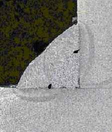


.jpg)